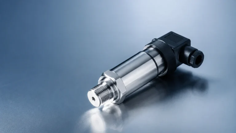
Flowsic500
Flowsic500
In the landscape of industrial gas measurement, the transition from mechanical to electronic metering has been accelerated by the demand for higher accuracy, lower maintenance, and better data integration. The Flowsic500, an ultrasonic gas flow meter designed specifically for natural gas distribution and industrial billing, represents a significant shift in how utilities and process plants manage their gas assets. Unlike traditional rotary or turbine meters, this technology utilizes acoustic signals to determine flow velocity, offering a solution that is free from moving parts and the wear-associated drift common in mechanical systems.
For engineers and facility managers familiar with level measurement technologies—such as those found on the Main Page of industrial instrumentation providers—the principles of ultrasonics are well-understood. However, applying these principles to high-pressure gas flow requires a specialized approach to transducer design and signal processing. This guide examines the technical foundations of the Flowsic500, its operational advantages, and the critical factors to consider during selection and installation.
Understanding Ultrasonic Gas Flow Measurement Principles
To appreciate the utility of the Flowsic500, one must first understand the "transit time difference" principle. This method relies on the fact that an ultrasonic pulse traveling in the direction of gas flow moves faster than a pulse traveling against the flow.
The Transit Time Method
Two ultrasonic transducers are positioned opposite each other at a specific angle relative to the gas flow. Both transducers act as both transmitters and receivers. The meter measures the time it takes for a sound pulse to travel from Transducer A to Transducer B (downstream) and from B to A (upstream).
If $t_{ab}$ is the downstream time and $t_{ba}$ is the upstream time, the difference between these two values is directly proportional to the velocity of the gas. Because the speed of sound in the gas is also calculated during this process, the meter can compensate for changes in gas composition, temperature, and pressure to a certain degree, although dedicated pressure and temperature sensors are typically integrated for full volume correction.
Path Configuration
The Flowsic500 typically employs a multi-path design. By sending pulses across different sections of the pipe diameter, the meter can account for non-uniform flow profiles. While large-scale custody transfer meters might use eight or more paths, the compact Flowsic500 optimizes its path geometry to maintain accuracy (often within ±0.5% to ±1.0%) while keeping the form factor small enough to replace traditional mechanical meters directly.
Technical Specifications and Design of the Flowsic500
The Flowsic500 is engineered to be a "plug-and-play" replacement for rotary and turbine meters. Its design focuses on modularity and ruggedness, which are essential for the harsh environments of gas pressure regulation stations and industrial boiler feeds.
Compact and Modular Construction
One of the defining features of this meter is its cartridge system. The measurement components are housed in a replaceable cartridge that can be swapped out without removing the entire meter body from the pipeline. This is a significant advantage for periodic recalibration; instead of sending the whole unit to a flow lab, a pre-calibrated cartridge can be installed, minimizing downtime.
Key Specifications (Typical):
* Nominal Diameters: DN50 (2"), DN80 (3"), DN100 (4"), and DN150 (6").
* Pressure Ratings: PN10/16, ANSI 150, and ANSI 300.
* Measurement Range: Turndown ratios often exceed 1:100, allowing for accurate measurement during both peak demand and low-flow pilot light periods.
* Power Supply: Battery-powered options are available, with life expectancies reaching up to 5–10 years, alongside 24V DC external power capabilities.
Material Compatibility
The meter bodies are typically constructed from ductile iron or cast steel, ensuring compatibility with standard natural gas distribution infrastructure. The transducers are designed to resist the buildup of "black powder" (iron sulfides and oxides) and other contaminants commonly found in gas pipelines.
Key Evaluation Criteria for Industrial Gas Metering
When selecting a gas flow meter like the Flowsic500, engineering teams must evaluate several performance metrics that go beyond simple price comparisons.
1. Rangeability and Turndown Ratio
Mechanical meters often struggle at very low flow rates due to the inertia required to start the internal components moving. The Flowsic500, having no moving parts, can detect extremely low velocities. This high turndown ratio ensures that "unaccounted-for gas" is minimized, which is critical for billing accuracy in industrial settings.
2. Pressure Drop
Because the Flowsic500 has a bore that is largely unobstructed, the pressure drop across the meter is negligible compared to rotary meters. This allows for lower upstream pressures and can reduce the energy requirements for compression in some industrial processes.
3. Maintenance and Longevity
Moving parts in turbine meters are susceptible to bearing wear and damage from debris. By eliminating these parts, the Flowsic500 reduces the total cost of ownership. The primary maintenance task involves checking the diagnostics provided by the meter’s internal electronics, which can signal when the transducers need cleaning or when the battery requires replacement.
Installation Best Practices and System Integration
While the Flowsic500 is designed to be more forgiving than older ultrasonic technologies, proper installation is still paramount to achieving the specified accuracy.
Piping Requirements
Traditional ultrasonic meters required long straight runs of pipe (e.g., 10 diameters upstream and 5 diameters downstream) to stabilize the flow profile. The Flowsic500 features internal flow conditioning or optimized path geometry that significantly reduces these requirements. In many cases, it can be installed with minimal straight pipe, though it is always recommended to avoid placing it immediately after high-turbulence components like partially closed valves or double elbows.
Orientation and Environment
The meter can generally be installed in horizontal or vertical orientations. However, in systems where liquid drop-out (condensate) is possible, horizontal installation with the electronics facing upward is preferred to prevent liquid from pooling on the transducer faces.
Integration with Level and Process Data
In a comprehensive industrial automation setup, gas flow data is rarely used in isolation. It is often integrated with level measurement data from storage tanks to calculate efficiency. For instance, a facility might use Welk's radar level meters to monitor liquid fuel or chemical feedstock levels while using a Flowsic500 to monitor natural gas consumption. Centralizing this data via Modbus or HART protocols allows for real-time energy balance calculations. For more information on integrating level sensors into these systems, engineers can review product options and application support on the Main Page.

Operational Limitations and Risk Mitigation
No measurement technology is universal. Understanding the limitations of the Flowsic500 is necessary to avoid performance issues.
* Gas Composition Changes: While ultrasonic meters are robust, extreme variations in gas composition (e.g., switching from natural gas to a high-hydrogen blend) may require configuration updates to ensure the sound velocity calculations remain accurate.
* Acoustic Noise: High-frequency noise generated by pressure-regulating valves located near the meter can interfere with the ultrasonic pulses. If a regulator is located immediately upstream, noise-attenuating equipment or specific distance requirements may be necessary.
* Liquid and Solids: While the meter is more resilient than mechanical types, heavy contamination or "slugs" of liquid can temporarily block the acoustic path, leading to a "signal loss" error. Proper filtration and separation upstream are standard best practices for all precision gas metering.
Selecting Between Flow and Level Measurement Technologies
In industrial process control, there is occasionally confusion between when to use flow measurement and when to use level measurement. The following table provides a practical selection reference for common scenarios encountered in gas and liquid handling.
| Application Scenario | Recommended Technology | Primary Measurement Metric |
| :— | :— | :— |
| Natural gas billing at a city gate | Ultrasonic Flow Meter (e.g., Flowsic500) | Standard Volume (Nm³ or SCF) |
| Monitoring LPG or LNG storage inventory | Radar or Hydrostatic Level Transmitter | Liquid Level / Volume (m or Liters) |
| High-pressure industrial burner feed | Ultrasonic or Vortex Flow Meter | Mass or Volumetric Flow Rate |
| Chemical dosing from a day tank | Ultrasonic Level Sensor / Small-bore Flow Meter | Level Change over Time / Flow Rate |
| Steam distribution monitoring | Vortex Flow Meter | Mass Flow (kg/h) |
For liquid-based applications, such as water treatment or chemical storage, Welk’s range of ultrasonic and radar level sensors provides the necessary accuracy for inventory management. However, for the gaseous phase and energy distribution, the Flowsic500 remains the industry standard for ultrasonic measurement.
Frequently Asked Questions (FAQ)
Q: Can the Flowsic500 be used for gases other than natural gas?
A: Yes, it is often used for air, nitrogen, and other non-corrosive gases. However, the calibration and material compatibility should be verified with the manufacturer for specific industrial gases.
Q: Does the meter require a flow computer?
A: The Flowsic500 has integrated volume correction capabilities (TZ or PTZ), meaning it can often perform the functions of a flow computer internally, providing corrected volume readings directly to the SCADA system.
Q: How does the accuracy compare to a turbine meter?
A: Under ideal conditions, both can be very accurate. However, the Flowsic500 maintains its accuracy over a much wider flow range and does not suffer from the mechanical wear that causes turbine meters to slow down over time.
Q: What happens if the battery dies?
A: The meter typically has a non-volatile memory that stores all configuration and totalizer data. Most models also feature a low-battery warning that triggers months before the battery is fully depleted.
Conclusion and Project Confirmation
Implementing a Flowsic500 into a gas distribution network or industrial facility offers a path toward higher reliability and reduced maintenance. Before proceeding with a project, technical stakeholders should confirm the following:
1. Process Conditions: Maximum and minimum flow rates, operating pressure, and temperature range.
2. Gas Quality: Presence of moisture, CO2 levels, or potential for solids.
3. Communication Requirements: Whether the system requires 4-20mA, pulse outputs, or digital protocols like Modbus.
4. Regulatory Compliance: Ensure the meter meets local weights and measures standards for custody transfer if used for billing.
By integrating advanced flow measurement with reliable level instrumentation—such as the solutions detailed on the Main Page—operators can achieve a holistic view of their process efficiency and resource consumption.