Vortex Flow Transmitter
Vortex Flow Transmitter
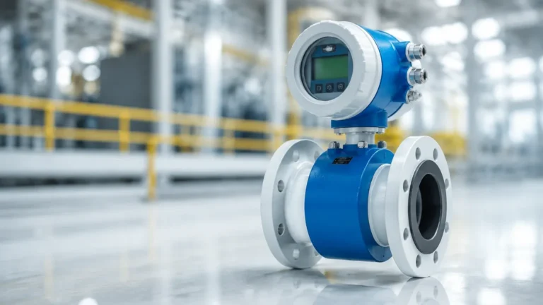
In the landscape of industrial process control, the accurate measurement of fluid movement is as critical as monitoring the levels within storage tanks. A vortex flow transmitter is a versatile and robust instrument designed to measure the flow rate of liquids, gases, and saturated or superheated steam. Known for having no moving parts, these devices offer high reliability and long-term stability across various industrial applications, from chemical processing to power generation.
As a professional manufacturer of industrial measurement instruments, Welk provides high-precision solutions that integrate seamlessly into automated systems. Understanding the technical foundations of vortex shedding and the specific installation requirements is essential for engineers and procurement professionals looking to optimize their process efficiency. For those evaluating a broader range of instrumentation, you can Review product options and application support on our main site to see how these technologies complement level measurement systems.
Measurement Principles: The von Kármán Effect
The operation of a vortex flow transmitter is based on the physical principle known as the von Kármán effect. When a fluid (liquid, gas, or steam) flows past a non-streamlined object, referred to as a "bluff body" or "shedder bar," it cannot follow the contours of the object on both sides. This results in the formation of alternating vortices (eddies) on either side of the body.
The Relationship Between Frequency and Velocity
These vortices are shed in a predictable, alternating pattern. The frequency at which these vortices are shed is directly proportional to the velocity of the fluid moving through the pipe. This relationship is defined by the Strouhal Number ($St$), a dimensionless constant that characterizes the oscillating flow mechanism. The fundamental equation is:
$$f = St \times \frac{V}{d}$$
Where:
* $f$: The frequency of the vortices (Hz).
* $St$: The Strouhal Number (constant for a specific bluff body shape over a wide range of Reynolds numbers).
* $V$: The velocity of the fluid (m/s).
* $d$: The width of the bluff body (m).
Because $St$ and $d$ are constant for a specific transmitter design, the frequency of the vortices is a linear representation of the flow velocity. By multiplying the velocity by the cross-sectional area of the pipe, the transmitter calculates the volumetric flow rate. To detect these pressure fluctuations caused by the vortices, the transmitter utilizes sensitive sensors, typically piezoelectric crystals or ultrasonic sensors, embedded within or located behind the shedder bar.
Key Components and Construction
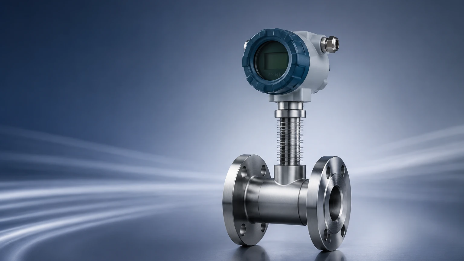
A vortex flow transmitter consists of three primary elements: the flow body, the shedder bar, and the electronics/transmitter head.
1. Flow Body: Usually constructed from stainless steel (316L) or specialized alloys like Hastelloy for corrosive environments. It is available in wafer-style (clamped between flanges) or flanged connections.
2. Shedder Bar: A precisely machined bar fixed across the diameter of the flow body. Its shape is critical to generating stable, detectable vortices.
3. Sensor Element: Piezoelectric sensors are the most common. They convert the mechanical pressure pulses of the vortices into electrical signals. Some advanced models use dual sensors to cancel out pipeline vibrations.
4. Transmitter Electronics: The "brain" of the device that processes the raw frequency signal, applies temperature and pressure compensation (in multivariable models), and outputs a standard industrial signal such as 4-20mA, HART, or Modbus.
Practical Selection Criteria
Choosing the right vortex flow transmitter requires an analysis of the process fluid and the environmental conditions. Unlike some other flow technologies, vortex meters are highly dependent on the Reynolds number of the fluid.
Selection Table: Application Suitability
| Parameter | Liquid Applications | Gas Applications | Steam Applications |
| :— | :— | :— | :— |
| Reynolds Number | Min 10,000 to 20,000 | Min 10,000 to 20,000 | Min 10,000 to 20,000 |
| Typical Accuracy | ±0.75% to ±1.0% of rate | ±1.0% to ±1.5% of rate | ±1.0% to ±2.0% of rate |
| Velocity Range | 0.5 – 7 m/s (1.6 – 23 ft/s) | 5 – 70 m/s (16 – 230 ft/s) | 5 – 80 m/s (16 – 260 ft/s) |
| Viscosity Limit | < 10 cP (centipoise) | N/A | N/A |
| Pressure Drop | Moderate | Low | Low |
Key Evaluation Factors
* Fluid Phase: Ensure the transmitter is calibrated for the specific phase. Multivariable vortex transmitters are preferred for steam because they include an internal temperature sensor (and sometimes a pressure sensor) to calculate mass flow.
* Turndown Ratio: Vortex meters typically offer a 10:1 to 30:1 turndown ratio. However, at very low flow rates, the vortices become too weak to detect, leading to a "low-flow cutoff."
* Material Compatibility: While 316 Stainless Steel is standard, aggressive chemicals may require Hastelloy or PTFE-lined bodies.
* Process Temperature: Standard models handle up to 250°C (482°F), while high-temperature versions can reach 400°C (752°F).
Installation Considerations
The accuracy of a vortex flow transmitter is heavily influenced by the flow profile. For the von Kármán effect to manifest correctly, the fluid must enter the meter in a stable, non-turbulent state.
Straight Pipe Run Requirements
To ensure a fully developed flow profile, specific lengths of straight pipe are required upstream and downstream of the transmitter. These are expressed in pipe diameters (D).
| Upstream Obstruction | Min. Upstream Straight Run | Min. Downstream Straight Run |
| :— | :— | :— |
| Single 90° Elbow | 20D | 5D |
| Two 90° Elbows (same plane) | 25D | 5D |
| Two 90° Elbows (different planes) | 40D | 5D |
| Reducer/Expander | 20D | 5D |
| Fully Open Valve | 20D | 5D |
| Control Valve | 50D | 5D |
*Note: If these distances cannot be met, a flow straightener or conditioner must be installed upstream.*
Orientation and Piping
* Vertical vs. Horizontal: Vortex meters can be installed in any orientation. However, for liquid applications, the flow must be upward in vertical pipes to ensure the pipe remains completely full. For steam or gas, horizontal mounting is common, but the sensor should be positioned to avoid condensate buildup.
* Vibration: Excessive pipeline vibration can interfere with the piezoelectric sensor. Ensure the pipe is properly supported on both sides of the transmitter.
* Gaskets: Ensure gaskets do not protrude into the flow stream, as this creates parasitic vortices that cause measurement errors.
Limitations and Potential Risks
While highly effective, vortex flow transmitters are not universal solutions. Engineers should be aware of the following limitations:
1. Low Flow Sensitivity: Below a certain velocity (the "cutoff"), the shedder bar does not produce detectable vortices. This makes them unsuitable for processes with extremely low flow rates or batching applications that start from zero.
2. Viscosity Constraints: High-viscosity liquids (typically above 10-15 cP) dampen the formation of vortices. Vortex meters are best suited for water-like liquids or light hydrocarbons.
3. Cavitation: In liquid applications, if the pressure drops too low at the shedder bar, cavitation can occur. This not only damages the instrument but also renders the readings inaccurate. Always ensure the process pressure is higher than the vapor pressure of the liquid.
4. Vibration Sensitivity: Although modern electronics use digital signal processing (DSP) to filter out noise, extreme mechanical vibration can still lead to "ghost flows" where the meter registers flow when the fluid is stationary.
Comparison with Other Technologies
| Feature | Vortex | Differential Pressure (Orifice) | Magnetic (Magmeter) |
| :— | :— | :— | :— |
| Moving Parts | None | None | None |
| Fluid Type | Liquid, Gas, Steam | Liquid, Gas, Steam | Conductive Liquids Only |
| Accuracy | High | Moderate | Very High |
| Pressure Drop | Permanent | Significant | Negligible |
| Maintenance | Low | High (impulse lines) | Low |
Compared to orifice plates, vortex transmitters offer a wider turndown and lower permanent pressure loss. Compared to magnetic flow meters, they are capable of measuring non-conductive fluids and gases, though they require higher velocities to operate.
Maintenance and Troubleshooting
Because there are no moving parts to wear out, maintenance for a vortex flow transmitter is minimal. However, periodic checks are recommended:
* Visual Inspection: Check the shedder bar for erosion or buildup of scale/debris. Any change in the shape of the bluff body will change the Strouhal Number and affect accuracy.
* Zero-Flow Check: With the pipe full but the flow stopped, the transmitter should read zero. If it shows a reading, it is likely detecting pipeline vibration or electrical noise.
* Electronics Verification: Most modern transmitters include internal self-diagnostics. Check for error codes related to sensor health or signal strength.
Frequently Asked Questions (FAQs)
Q: Can a vortex flow transmitter measure wet steam?
A: Vortex meters are excellent for saturated and superheated steam. However, if the steam is "wet" (contains water droplets), the meter will typically measure the volumetric flow of the total mixture, which can lead to inaccuracies in mass flow calculations. Multivariable versions are better equipped to handle varying steam qualities.
Q: What happens if the Reynolds number is too low?
A: If the Reynolds number drops below the linear range (usually <10,000), the relationship between vortex frequency and velocity becomes non-linear. The transmitter may either provide highly inaccurate data or drop the signal to zero.
Q: Is it necessary to insulate the transmitter?
A: For high-temperature applications like steam, the flow body should be insulated to protect personnel and conserve energy. However, the transmitter electronics housing must remain uninsulated to allow for heat dissipation, often utilizing a "neck" extension to keep the electronics away from the heat source.
Conclusion
The vortex flow transmitter remains a cornerstone of industrial flow measurement due to its versatility and lack of moving parts. By adhering to strict installation guidelines—particularly regarding straight pipe runs—and ensuring the fluid properties fall within the required Reynolds number range, operators can achieve precise and reliable data for years.
For comprehensive process control, integrating flow data with accurate level monitoring is essential. To explore how our level measurement instruments can complement your flow systems, visit our Main Page for detailed technical specifications and engineering support.