Capacitive Probes
Capacitive Probes
In the landscape of industrial automation and process control, capacitive probes represent one of the most versatile and established technologies for level measurement. These instruments are employed across a vast array of sectors, including water treatment, chemical processing, food and beverage, and oil and gas. Their popularity stems from a lack of moving parts, high durability in aggressive environments, and the ability to handle both liquids and bulk solids.
Selecting the correct capacitive probe requires an understanding of the underlying physics, the dielectric properties of the media, and the specific mechanical constraints of the vessel. This guide provides a comprehensive technical overview of capacitive level measurement to assist engineers in making informed procurement and installation decisions.
The Principle of Capacitive Level Measurement
Capacitive level measurement is based on the electrical principle of a capacitor. In a standard electronic circuit, a capacitor consists of two conductive plates separated by an insulating material known as a dielectric. The ability of this setup to store an electrical charge is defined as capacitance ($C$).
In an industrial tank application, the capacitive probe (the electrode) acts as one plate of the capacitor, while the vessel wall (if metallic and conductive) acts as the second plate. The material stored in the tank serves as the dielectric. The basic formula for capacitance is:
$$C = \epsilon_0 \epsilon_r \frac{A}{d}$$
Where:
* $C$: Capacitance in Farads.
* $\epsilon_0$: Permittivity of free space (constant).
* $\epsilon_r$: Dielectric constant (relative permittivity) of the material between the plates.
* $A$: The surface area of the plates.
* $d$: The distance between the plates.
When the level of the medium in the tank rises, it displaces the air or gas (which has a dielectric constant of approximately 1.0). Since most liquids and solids have a higher dielectric constant than air, the total capacitance of the system increases as the probe is submerged. The electronics in the probe head convert this change in capacitance into a proportional linear signal, typically 4-20 mA, or a switching output for point level detection.
The Role of the Dielectric Constant ($\epsilon_r$)
The dielectric constant of the medium is the most critical factor in capacitive measurement. For non-conductive materials (like oils or plastic pellets), the probe measures the change in capacitance caused by the material's $\epsilon_r$. For conductive materials (like water-based solutions or acids), the probe must be insulated (usually with PTFE or PFA). In this case, the insulation itself acts as the dielectric, and the measurement becomes a function of the covered surface area of the probe.
Structural Variations of Capacitive Probes
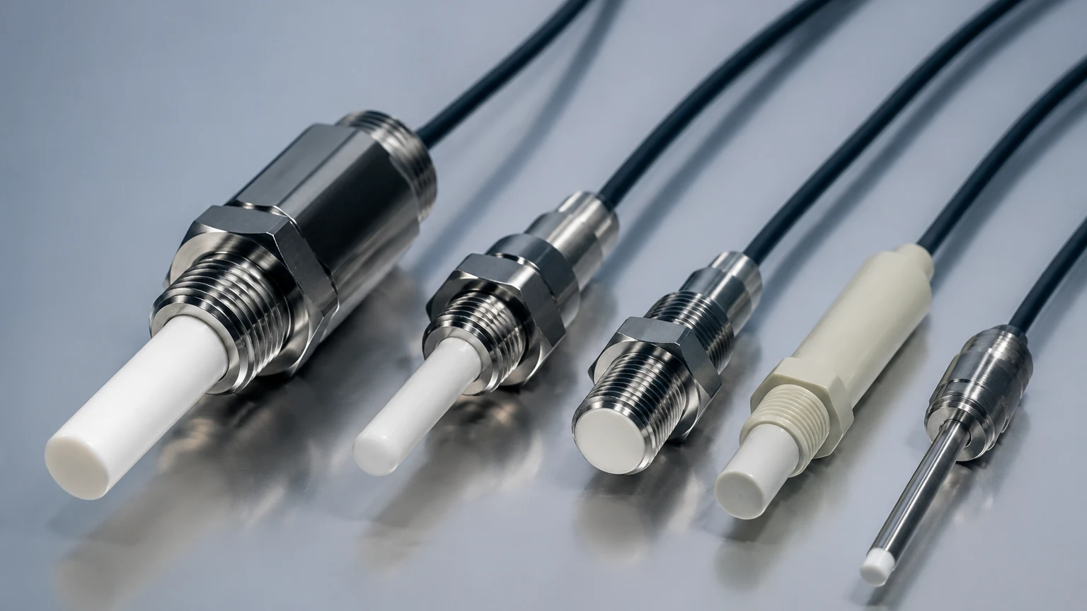
Capacitive probes are not "one size fits all." The mechanical design must be matched to the tank geometry and the physical characteristics of the media.
1. Rod Probes
Rod probes are rigid electrodes typically used for shorter distances, usually up to 3 or 4 meters. They are ideal for point level detection (high or low alarms) and continuous measurement in smaller process vessels. Because they are rigid, they can withstand some degree of turbulence or agitation within the tank without swaying.
2. Cable Probes
For deep tanks or tall silos (reaching up to 30 meters or more), rigid rods are impractical. Cable probes utilize a flexible stainless steel cable, often weighted at the bottom to keep it taut. These are standard in the bulk solids industry for measuring grain, powders, or ores in large silos.
3. Coaxial Probes
In non-metallic tanks (such as plastic or fiberglass) or when the medium has a very low dielectric constant, a coaxial probe (or a probe with a reference tube) is used. The probe is surrounded by an outer tube, which acts as the second electrode. This ensures a constant distance ($d$) and a stable reference, regardless of the tank's material or shape.
Practical Selection Criteria
Choosing the right instrument involves evaluating the chemical compatibility, physical state, and electrical properties of the substance. For a detailed look at specific hardware options, engineers can visit the Main Page of the manufacturer’s catalog.
Selection Table: Media vs. Probe Type
| Medium Type | Dielectric Constant ($\epsilon_r$) | Recommended Probe Type | Insulation Required? |
| :— | :— | :— | :— |
| Deionized Water | ~80 | Rod or Cable | Yes (PTFE/PFA) |
| Diesel Fuel | ~2.1 | Coaxial or Rod | No |
| Plastic Pellets | 1.1 – 2.0 | Cable (with gravity weight) | No |
| Concentrated Acid | High | Rod (Corrosion resistant) | Yes (High-grade PFA) |
| Cement Powder | 4.0 – 6.0 | Heavy-duty Cable | No |
Temperature and Pressure Considerations
Standard capacitive probes can typically handle temperatures up to 100°C and pressures up to 20 bar. However, for high-pressure steam applications or high-temperature reactors (up to 400°C), specialized ceramic-to-metal seals and cooling fins are required to protect the electronics in the housing.
Installation Considerations
Proper installation is paramount to the accuracy of capacitive probes. Because the technology relies on the relationship between the probe and the reference (the tank wall), the following guidelines should be followed:
1. Distance from Walls: The probe should be installed at a fixed distance from the tank wall. If the probe is too close, the base capacitance may be too high, reducing the sensitivity to level changes. A minimum distance of 300 mm is usually recommended for non-coaxial probes.
2. Avoid Inflow Streams: Never install a probe directly in the path of the material filling the tank. The falling material will cause false readings or physical damage to the probe.
3. Grounding: In metallic tanks, the probe must be electrically bonded to the tank. In non-metallic tanks, a reference electrode (grounding rod) or a coaxial sleeve must be used to provide the return path for the electrical field.
4. Dead Zones: Every probe has a "dead zone" at the top (near the mounting thread) and at the bottom (near the end of the rod or weight). No measurement can occur in these areas. Engineers must account for these offsets when calibrating the 0% and 100% points.
Limitations and Managing Risks
While highly effective, capacitive probes have specific limitations that must be managed through engineering design.
Coating and Buildup
One of the primary challenges is the buildup of conductive material on the probe. If a conductive liquid leaves a film on the insulation, the probe may continue to "see" the liquid even after the level has dropped.
* Solution: Use "Active Shield" or "RF Admittance" technology. These advanced capacitive probes include a secondary shield section that prevents current leakage through the buildup, ensuring the sensor only measures the actual level.
Moisture in Solids
In bulk solids, changes in moisture content can significantly alter the dielectric constant of the material. For example, dry sand has a much lower $\epsilon_r$ than wet sand.
* Solution: If moisture levels fluctuate wildly, capacitive probes may require frequent recalibration. In such cases, radar-based measurement might be a more stable alternative.
Comparison: Capacitive vs. Other Technologies
| Feature | Capacitive Probes | Ultrasonic | Radar (GWR) |
| :— | :— | :— | :— |
| Moving Parts | None | None | None |
| Contact | Contacting | Non-contact | Contacting |
| Vacuum Support | Excellent | Poor | Excellent |
| Heavy Foam | Variable (Depends on $\epsilon_r$) | Poor | Good |
| Cost | Low to Moderate | Moderate | High |
Frequently Asked Questions (FAQ)
Q: Can capacitive probes be used in plastic tanks?
A: Yes, but since the tank wall is not conductive, you must use either a coaxial probe or install a second rod to act as the ground reference.
Q: How do I calibrate a capacitive probe?
A: Most modern probes feature a "push-button" calibration. You typically set the "Zero" point when the tank is empty and the "Span" point when the tank is at least 80% full. Digital versions allow for calibration via HART or Bluetooth protocols.
Q: Does the probe need to be cleaned?
A: If the medium is non-coating (like clean oil), maintenance is minimal. If the medium is sticky or viscous, periodic inspection is recommended unless an active-shield probe is used.
Q: What is the maximum length for a cable probe?
A: Standard cable probes can reach 30 to 35 meters. Beyond this, the mechanical load on the tank roof and the cable itself becomes a significant structural concern.
Conclusion
Capacitive probes remain a cornerstone of industrial level sensing due to their reliability and adaptability. By understanding the dielectric properties of the process media and selecting the appropriate probe geometry, facilities can achieve high-accuracy measurement with minimal maintenance. For further technical specifications or to request a quote for customized level solutions, please refer to the Main Page for comprehensive product support.