Forberg Scientific
Forberg Scientific
In the complex landscape of industrial process control, the selection and procurement of instrumentation require a balance between technical precision and supply chain reliability. Organizations such as Forberg Scientific have established themselves as significant players in the distribution of pressure, flow, and level measurement technologies across various industrial sectors. For engineers and procurement professionals, understanding the technical nuances of these instruments is as critical as selecting a reputable distributor. This guide explores the fundamental principles of level measurement, selection criteria, and installation best practices essential for maintaining operational efficiency in modern process environments.
Fundamental Principles of Level Measurement
Before selecting a specific instrument through a distributor like Forberg Scientific, it is vital to understand the physics governing different measurement technologies. Level measurement is generally categorized into continuous measurement and point level detection, utilizing various mechanical and electronic principles.
Radar Level Measurement (ToF)
Radar level transmitters operate on the Time-of-Flight (ToF) principle. The device emits high-frequency microwave pulses (typically in the 26 GHz or 80 GHz range) that travel at the speed of light. When these pulses hit the surface of the medium, they are reflected back to the sensor. The distance is calculated based on the time interval between transmission and reception.
* Non-Contact Radar: Ideal for corrosive or abrasive media as the sensor does not touch the material. It is highly effective in environments with fluctuating temperatures and pressures.
* Guided Wave Radar (GWR): Uses a probe or cable to guide the microwave signal. This is particularly useful in liquids with low dielectric constants or in applications with heavy foam or turbulence.
Ultrasonic Level Measurement
Similar to radar, ultrasonic sensors use the ToF principle but employ sound waves instead of electromagnetic waves. A transducer emits an ultrasonic pulse (usually between 20 kHz and 200 kHz), which reflects off the liquid surface.
Because sound requires a medium to travel, ultrasonic sensors are sensitive to air temperature, vapor layers, and vacuum conditions. They are most commonly used in water treatment and simple chemical storage where the atmosphere remains relatively stable.
Hydrostatic Level Measurement
Hydrostatic transmitters measure the pressure exerted by a liquid column at a specific point. The relationship is defined by the formula: $P = \rho \cdot g \cdot h$, where $P$ is pressure, $\rho$ (rho) is the density of the liquid, $g$ is gravity, and $h$ is the height of the liquid.
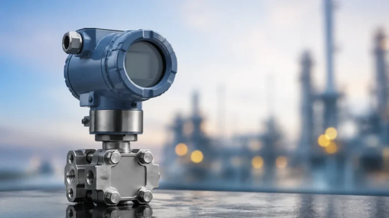
In open tanks, a simple submersible or flange-mounted pressure transmitter is used. In pressurized vessels, a differential pressure (DP) approach is required to subtract the head pressure of the gas space from the total pressure at the bottom of the tank.
Magnetic Level Gauges
Magnetic level gauges (MLGs) utilize a float containing an internal magnet assembly that moves within a bypass chamber mounted to the side of a vessel. As the float rises and falls with the liquid level, the magnetic field interacts with an external indicator (flags or a follower) to provide a visual representation of the level. These are highly valued in high-pressure or high-temperature applications where glass gauges would be unsafe.
Selection Criteria for Industrial Level Instruments
When evaluating options provided by distributors like Forberg Scientific, engineers must confirm several process parameters to ensure the longevity and accuracy of the instrument. For a detailed look at specific product specifications, professionals often refer to the Main Page of specialized manufacturers to compare technical data sheets.
Media Characteristics
* Dielectric Constant (εr): For radar measurement, the dielectric constant of the medium determines the strength of the reflected signal. Liquids with εr < 1.4 often require guided wave radar.
* Viscosity and Coating: Highly viscous liquids can coat probes, leading to false readings in contact-based systems like GWR or capacitance probes.
* Chemical Compatibility: Wetted parts must be resistant to the process media. Common materials include 316L Stainless Steel, PTFE, Hastelloy, and PVDF.
Process Conditions
* Temperature: Standard sensors may operate up to 80°C, while specialized high-temperature versions can withstand over 400°C.
* Pressure: Hydrostatic and magnetic gauges are often rated for high-pressure environments (up to 400 bar), whereas ultrasonic sensors are generally limited to near-atmospheric pressures.
* Turbulence and Foam: Foam can absorb ultrasonic and radar signals. In such cases, GWR or displacement-based technologies are preferred.
Technology Comparison Table
| Technology | Accuracy | Max Range | Contact/Non-Contact | Primary Limitation |
| :— | :— | :— | :— | :— |
| Radar (80 GHz) | ±1 mm | 30m – 120m | Non-Contact | High initial cost |
| Ultrasonic | ±0.25% of range | 15m – 20m | Non-Contact | Sensitive to vapors/vacuum |
| Hydrostatic | ±0.1% of span | Unlimited | Contact | Dependent on fluid density |
| Guided Wave Radar | ±2 mm | 75m | Contact | Probe susceptible to buildup |
| Magnetic Gauge | ±5 mm | 6m (standard) | Contact (Float) | Mechanical wear over time |
Installation Considerations and Best Practices
Proper installation is as critical as the technology selection. Even the most advanced sensor from a premium distributor like Forberg Scientific will fail if installed incorrectly.
1. Nozzle Geometry: For radar and ultrasonic sensors, the nozzle height should be kept to a minimum to prevent signal interference. The diameter of the nozzle must be large enough to allow the signal beam to clear the bottom edge without reflecting off the nozzle walls.
2. Dead Zones (Blocking Distance): Every ToF sensor has a "dead zone" near the transducer face where measurements cannot be taken. Ensure the maximum liquid level never enters this zone.
3. Internal Obstructions: Avoid installing sensors directly above agitators, heating coils, or ladders. If obstructions are unavoidable, use software-based "false echo suppression" to map out these static reflections.
4. Stilling Wells: In applications with heavy turbulence or low dielectric liquids, installing the sensor inside a stilling well or bypass pipe can provide a stable surface for measurement.
5. Mounting Position: Sensors should generally be mounted 1/6th to 1/3rd of the tank diameter away from the wall to avoid side-wall interference while staying clear of the center (where vortexes form during filling/emptying).

Limitations and Common Risks
While modern instrumentation is robust, there are inherent risks that must be managed:
* Density Fluctuations: Hydrostatic sensors are calibrated based on a specific fluid density. If the process involves mixing different chemicals or significant temperature swings that change the density, the level reading will drift.
* Condensation and Buildup: In high-humidity environments, condensation on an ultrasonic transducer face can "blind" the sensor. Radar sensors with PTFE drip shields are better suited for these conditions.
* Signal Attenuation: Heavy dust in solids measurement or thick foam in liquid measurement can attenuate the signal of non-contact sensors. In these scenarios, mechanical or contact-based electronic measurement is often more reliable.
Sourcing and Technical Support
When working with a technical distributor like Forberg Scientific, the value lies in their ability to provide local support and inventory. However, the end-user remains responsible for confirming that the supplied specifications meet the actual site conditions. It is recommended to verify:
* Certification Requirements: Does the site require ATEX, IECEx, or SIL2/3 ratings?
* Integration Protocols: Will the device communicate via 4-20mA HART, Profibus, or Modbus?
* Lead Times: For critical applications, ensure that spare parts or replacement units are readily available.
Frequently Asked Questions (FAQ)
Q: Can radar level meters work in a vacuum?
A: Yes. Unlike ultrasonic sensors, radar waves do not require a medium for travel and are unaffected by vacuum conditions.
Q: How often should hydrostatic level transmitters be calibrated?
A: While many modern transmitters have low drift rates, an annual calibration check is recommended, especially in applications where fluid density may change over time.
Q: What is the benefit of 80 GHz radar over 26 GHz?
A: 80 GHz radar has a much narrower beam angle, which allows it to avoid internal tank obstructions more easily and provides better accuracy in small vessels or through narrow nozzles.
Q: Are magnetic level gauges suitable for dirty liquids?
A: If the liquid contains magnetic particles (like iron filings), they can stick to the internal float magnet and impede movement. For general "dirty" liquids, a bypass chamber with sufficient clearance is usually acceptable, provided there is a regular cleaning schedule.
Q: Does Forberg Scientific provide on-site installation?
A: While distributors typically provide technical consultation and equipment, on-site installation is often handled by specialized contractors or the facility's maintenance team, guided by the manufacturer's documentation.
By adhering to these engineering principles and carefully evaluating the specific needs of the application, process professionals can ensure that the instruments they source—whether through Forberg Scientific or directly from manufacturers—provide accurate, reliable data for years to come.