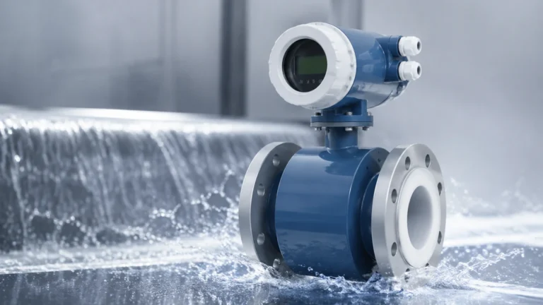
Drucktransmitter
Drucktransmitter
In the field of industrial process control and automation, the measurement of liquid levels is a fundamental requirement for safety, efficiency, and inventory management. Among the various technologies available, the use of a "drucktransmitter" (pressure transmitter) for hydrostatic level measurement remains one of the most prevalent and reliable methods. By measuring the force exerted by a liquid column at a specific point, these instruments provide accurate data that can be converted into level, volume, or mass readings.
This guide explores the engineering principles behind pressure-based level measurement, the technical specifications of modern transmitters, and the practical considerations necessary for selecting and installing these devices in industrial environments. For those seeking specific product specifications or customized measurement solutions, visiting the Main Page provides a comprehensive overview of current instrumentation options.
Measurement Principles of Hydrostatic Level Sensing
The operation of a drucktransmitter in level applications is based on the hydrostatic paradox, which states that the pressure at a specific depth in a static liquid is proportional to the height of the liquid column above it, regardless of the vessel's shape.
The Hydrostatic Formula
The relationship is defined by the formula:
P = ρ · g · h
Where:
* P is the hydrostatic pressure (measured in Pascals or Bar).
* ρ (rho) is the density of the liquid (kg/m³).
* g is the acceleration due to gravity (approximately 9.81 m/s²).
* h is the height of the liquid column (meters).
In a standard industrial application, gravity is constant. Therefore, if the density of the medium is known and remains stable, the pressure measured by the drucktransmitter is a direct indicator of the liquid level. For example, a water column (density ≈ 1000 kg/m³) with a height of 10 meters will exert a pressure of approximately 1 bar (100 kPa) at the base.
Gauge vs. Absolute Pressure
When selecting a drucktransmitter, engineers must distinguish between gauge and absolute pressure measurement:
1. Gauge Pressure (Relative): The sensor is vented to the atmosphere. It measures the pressure of the liquid minus the ambient atmospheric pressure. This is the most common type for open tanks or reservoirs.
2. Absolute Pressure: The sensor is referenced against a vacuum. This is rarely used for level measurement unless the process requires monitoring in a vacuum-sealed environment.
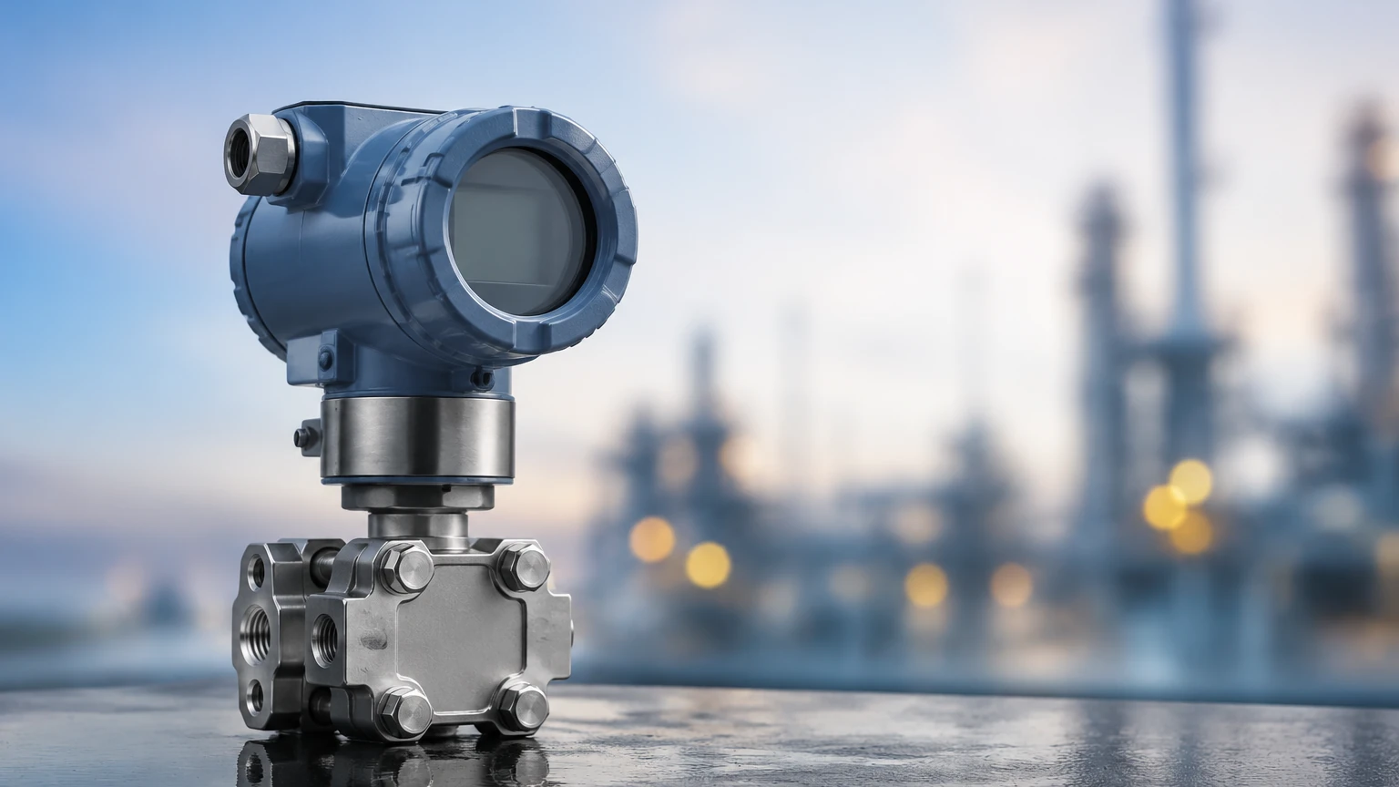
3. Differential Pressure (DP): Used in pressurized or closed vessels. Two sensors (or one sensor with two ports) measure the pressure at the bottom and the pressure in the gas phase (headspace) above the liquid. The difference between the two is the hydrostatic pressure of the liquid alone.
Technical Variations of Drucktransmitter Units
Pressure transmitters are designed in various form factors to suit different installation environments and media characteristics.
Submersible Level Transmitters
Often referred to as probe-style transmitters, these are designed to be lowered directly into the medium. They consist of a sensor head sealed to an IP68 rating and a specialized cable that includes a vent tube. This tube allows the internal side of the sensing diaphragm to remain at atmospheric pressure, ensuring accurate gauge pressure readings even at the bottom of a deep well or tank.
Externally Mounted Transmitters
These units are mounted to the outside of a tank via a threaded connection or a flange. They are ideal for applications where the sensor needs to be isolated from the medium for maintenance or where the tank already has existing process connections. In the chemical industry, these often utilize a flush diaphragm to prevent viscous media from clogging the sensor port.
Sensor Cell Technologies
* Piezoresistive Silicon: These sensors use a silicon chip with diffused resistors. They are highly sensitive and offer excellent long-term stability, making them suitable for clean water and light oils.
* Ceramic Capacitive: These feature a ceramic diaphragm that moves relative to a base plate, changing the capacitance. They are exceptionally rugged, resistant to abrasive particles, and can handle high overpressure peaks, which is critical in wastewater and slurry applications.
Practical Selection Table
Choosing the right drucktransmitter requires balancing technical requirements with cost-effectiveness. The following table provides a comparison based on common industrial scenarios.
| Application | Recommended Sensor Type | Diaphragm Material | Key Consideration |
| :— | :— | :— | :— |
| Deep Boreholes/Wells | Submersible (Probe) | Stainless Steel 316L | High tensile strength cable and lightning protection. |
| Chemical Storage Tanks | External Flanged | Tantalum or PTFE coated | Chemical compatibility and corrosion resistance. |
| Wastewater Treatment | Ceramic Submersible | Ceramic (Al2O3) | Resistance to grit, solids, and turbulent flow. |
| Pressurized Vessels | Differential Pressure | 316L or Hastelloy | Compensation for headspace pressure. |
| Food & Beverage | Flush Diaphragm | 316L (Electropolished) | Hygienic connections (Tri-clamp) and CIP/SIP compatibility. |
Installation Considerations for Accurate Measurement
Even the most accurate drucktransmitter will provide faulty data if installed incorrectly. Engineering teams should adhere to the following guidelines:
Positioning and Turbulence
In tanks with agitators or high-velocity inflow, the transmitter should not be placed directly in the path of the moving liquid. Turbulence can cause pressure fluctuations that the sensor interprets as level changes. If a submersible sensor is used in a turbulent tank, it should be installed inside a "stilling well" (a perforated pipe) to dampen the movement of the liquid.
The Atmospheric Vent Tube
For submersible cables, the integrity of the vent tube is paramount. If moisture enters the vent tube, it can block the passage of air or cause internal corrosion. Installers must use a moisture filter or a specialized junction box that allows the tube to breathe while preventing water ingress. The end of the tube should never be submerged or placed in a location where it might collect condensation.
Avoiding Sediment
Transmitters should be installed at least 50mm to 100mm above the bottom of the tank or well. This prevents the sensor diaphragm from being buried in silt, sand, or sludge, which would lead to measurement drift or total sensor failure.
Temperature Compensation
Liquid density changes with temperature. While most modern drucktransmitter units include internal temperature compensation for the sensor's electronics, they cannot automatically compensate for the change in the liquid's density. In applications with wide temperature swings, a secondary temperature sensor and a PLC (Programmable Logic Controller) may be required to calculate the corrected level.
Limitations and Engineering Boundaries
While hydrostatic measurement is versatile, it is not a "one-size-fits-all" solution. Engineers must be aware of its inherent limitations:
1. Density Sensitivity: If the process involves mixing different liquids with varying densities, the drucktransmitter will report a change in level even if the physical height remains the same. In such cases, non-contact technologies like radar or ultrasonic sensors may be more appropriate.
2. Pressurized Tanks: A standard gauge pressure transmitter cannot distinguish between liquid pressure and gas headspace pressure. In closed systems, a differential pressure setup is mandatory.
3. Mechanical Wear: Diaphragms are thin and can be damaged by mechanical cleaning or high-pressure water jets. Protective cages are often used on submersible models to mitigate this risk.
Maintenance and Calibration
To maintain the reliability of a drucktransmitter, a routine maintenance schedule is recommended. This includes:
* Visual Inspection: Checking for build-up on the diaphragm or signs of corrosion on the housing.
* Zero-Point Calibration: Over time, sensors may experience a slight "zero drift." Periodically checking the output when the tank is empty (or the sensor is pulled out of the water) ensures the baseline remains accurate.
* Signal Validation: Verifying that the 4-20mA or digital signal (HART, Modbus) matches the physical level observed in the tank.
For complex industrial environments where multiple measurement technologies are integrated, reviewing various sensor types on the Main Page can help in designing a redundant and robust system.
Frequently Asked Questions (FAQs)
Q: Can a drucktransmitter be used for boiling liquids?
A: It is possible, but difficult. Boiling liquids have fluctuating densities due to bubble formation (aeration), which will cause the pressure reading to be lower than the actual physical level. Furthermore, the steam in the headspace may require a differential pressure transmitter with remote seals to protect the electronics from high temperatures.
Q: How do I protect the sensor from lightning strikes in outdoor installations?
A: Many high-quality submersible transmitters include built-in surge protection. Additionally, using a grounded junction box and shielded cabling is standard practice for boreholes and large outdoor reservoirs.
Q: What is the difference between a 2-wire and 4-wire drucktransmitter?
A: Most modern industrial transmitters are 2-wire devices, meaning the power supply and the 4-20mA output signal share the same pair of wires. 4-wire devices have separate pairs for power and signal, which is usually only necessary for high-power applications or specific digital communication requirements.
Q: Is it possible to measure the level of a corrosive acid with a pressure transmitter?
A: Yes, provided the wetted materials are compatible. This typically involves using a transmitter with a ceramic diaphragm and a PVDF or PTFE housing, or a stainless steel transmitter with a Tantalum diaphragm and specialized chemically resistant cables.
Conclusion
The drucktransmitter remains a cornerstone of industrial level measurement due to its simplicity, cost-effectiveness, and reliability. By understanding the relationship between pressure and density, and by following strict installation protocols, engineering teams can achieve high-precision monitoring in even the most demanding environments. Whether the application involves clean water management or complex chemical processing, selecting the appropriate sensor material and mounting style is the key to long-term operational success.