Vector Systems Usa
Vector Systems Usa
In the landscape of industrial process control, the integration of complex mechanical systems with precision instrumentation is the cornerstone of operational efficiency. Vector Systems USA has established itself as a significant entity in the design and fabrication of process skids, particularly those involving ammonia handling, fuel gas conditioning, and emissions control systems like Selective Catalytic Reduction (SCR). For engineers and plant managers, understanding how these integrated systems interact with level measurement technologies is essential for ensuring safety, compliance, and process stability.
Industrial level measurement is not a one-size-fits-all discipline. When dealing with the specialized modules often associated with Vector Systems USA—such as aqueous ammonia storage or high-pressure fuel gas units—the choice of level sensor can dictate the reliability of the entire process loop. This article explores the technical synergy between modular process systems and modern level measurement instruments, providing a guide for selection and implementation.
The Role of Level Measurement in Integrated Process Systems
Modular systems, often referred to as "skids," are self-contained process units that are pre-engineered and tested before arriving at a facility. Vector Systems USA specializes in these types of configurations. Within these skids, level measurement serves several critical functions:
1. Inventory Management: Monitoring the volume of reagents like ammonia or urea in SCR systems to ensure uninterrupted emissions control.
2. Process Safety: Preventing overfill conditions in pressurized vessels, which could lead to hazardous leaks or equipment damage.
3. Pump Protection: Ensuring that pumps do not run dry by maintaining a minimum liquid level in suction tanks.
4. Interface Control: In fuel gas conditioning, separating liquids from gas streams requires precise detection of the interface between different fluid phases.
To achieve these goals, engineers must select instruments that can withstand the chemical properties of the media and the physical conditions (temperature and pressure) of the environment.
Core Technologies for Fluid Management
Before selecting a specific instrument for a system, it is vital to understand the underlying measurement principles. Each technology offers distinct advantages depending on the fluid's dielectric constant, density, and turbulence.
Radar Level Measurement (Non-Contact and Guided)
Radar technology is widely considered the gold standard for challenging chemical applications. It operates on the Time-of-Flight (ToF) principle. The sensor emits a high-frequency microwave signal that travels to the liquid surface and reflects back to the receiver. The distance is calculated based on the time taken for the signal to return.
* Non-Contact Radar: Ideal for corrosive liquids like ammonia. Since the sensor does not touch the media, maintenance requirements are significantly reduced. Modern 80GHz radar units offer narrow beam angles, which are beneficial in the tight internal spaces of modular skids.
* Guided Wave Radar (GWR): This utilizes a probe or cable to guide the microwave signal. GWR is particularly effective in low-dielectric fluids or applications with heavy foam, as the probe ensures the signal reaches the liquid surface without dissipation.
Magnetic Level Gauges (MLG)
Magnetic level gauges are frequently used on the exterior of tanks within systems designed by Vector Systems USA. They provide a clear, visual indication of level without requiring power. The system consists of a bypass chamber connected to the vessel. Inside the chamber, a float containing a high-intensity magnet moves with the liquid level. Outside the chamber, a series of bi-color flags or a magnetic follower tracks the float’s position.
MLGs are often paired with reed switches or magnetostrictive transmitters to provide both local visual confirmation and a remote 4-20mA signal to the central control system.
Hydrostatic Pressure Transmitters
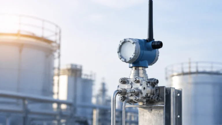
Hydrostatic measurement relies on the principle that the pressure at the bottom of a vessel is proportional to the height of the liquid column above it. The formula used is $P = \rho gh$, where $P$ is pressure, $\rho$ is the fluid density, $g$ is gravity, and $h$ is the height. This method is highly reliable for vented tanks with stable fluid densities. For pressurized tanks, a differential pressure (DP) transmitter is used to compensate for the headspace pressure.
Selection Criteria for Level Instruments in Vector Systems USA Applications
When integrating level sensors into a Vector Systems USA skid or a similar industrial module, the following selection table provides a baseline for engineering decisions:
| Application Type | Recommended Technology | Primary Benefit | Limitations |
| :— | :— | :— | :— |
| Aqueous Ammonia Storage | Non-Contact Radar | Corrosion resistance; no moving parts | High cost compared to pressure |
| Fuel Gas Separators | Guided Wave Radar | Accurate interface detection | Probe can accumulate debris |
| High-Pressure Steam | Magnetic Level Gauge | Visual redundancy; high temp rating | Moving parts (float) can stick |
| Water Treatment Tanks | Ultrasonic Sensor | Cost-effective; non-contact | Sensitive to foam and vapors |
| Chemical Dosing Skids | Hydrostatic Transmitter | Simple installation; robust | Density changes affect accuracy |
Material Compatibility
In systems handling anhydrous or aqueous ammonia, material selection is paramount. Standard stainless steel (316L) is generally acceptable, but seals must be carefully chosen. PTFE or Kalrez gaskets are often required to prevent degradation. When specifying instruments for a Vector Systems USA project, always confirm that the wetted parts are compatible with the specific chemical concentration and temperature profile.
Installation and Engineering Considerations
Proper installation is as critical as instrument selection. In the compact environment of a modular skid, space is at a premium, and improper placement can lead to false readings.
1. Nozzle Positioning: For radar and ultrasonic sensors, the nozzle should be located away from the tank wall and any internal obstructions like agitators or heating coils. A general rule is to keep the sensor at least 200 mm (approx. 8 inches) away from the wall to prevent signal interference.
2. Bypass Chambers: When using magnetic level gauges or GWR in bypass chambers, the chamber must be perfectly vertical. Any tilt can cause the float or probe to bind, leading to inaccurate readings.
3. Venting and Equalization: For hydrostatic and magnetic systems, ensuring the headspace is properly vented or equalized is essential. In pressurized systems, the "wet leg" or "dry leg" of a differential pressure transmitter must be maintained to prevent zero-shift errors.
4. Stilling Wells: In tanks with high turbulence or surface agitation, a stilling well (a perforated pipe) can be used to provide a calm surface for the level sensor to measure. This is particularly common in fuel oil and water treatment applications.

Limitations and Operational Challenges
While modern instrumentation is highly advanced, certain physical limitations remain:
* Dielectric Constants: Radar relies on the reflectivity of the fluid. Fluids with a very low dielectric constant ($ε_r < 1.4$) may require guided wave radar or specialized high-sensitivity non-contact units.
* Vapor and Gas Layers: In ammonia systems, the presence of heavy vapors can attenuate ultrasonic signals. In such cases, radar is the preferred alternative as microwaves are unaffected by gas compositions.
* Build-up and Scaling: In wastewater or heavy oil applications, material can build up on the sensor face or probe. Self-cleaning functions or non-contact designs are necessary to prevent "signal loss" or "frozen" readings.
Frequently Asked Questions (FAQ)
Q: Can I use an ultrasonic sensor for ammonia level measurement?
A: It is generally not recommended. Ammonia vapors can change the speed of sound, leading to significant measurement errors. Furthermore, ammonia can be corrosive to the materials used in many standard ultrasonic transducers. Radar is a much more reliable choice for this application.
Q: What is the maintenance schedule for a magnetic level gauge?
A: MLGs are relatively low-maintenance. However, it is recommended to flush the bypass chamber annually to remove any sediment that could impede float movement. The float itself should be inspected for integrity if the process fluid is particularly aggressive.
Q: How does temperature affect hydrostatic level measurement?
A: Temperature affects the density of the liquid. Since hydrostatic sensors measure pressure and calculate level based on a fixed density, a significant temperature increase (which lowers density) will cause the sensor to under-report the actual level. Temperature compensation via an integrated RTD is often required for high-precision applications.
Q: Why is 80GHz radar preferred over 26GHz radar in skids?
A: 80GHz radar has a much narrower beam angle (often as small as 3 degrees). In the small tanks typical of modular skids, this prevents the signal from hitting the tank walls or nozzles, resulting in a much cleaner signal and easier commissioning.
Conclusion
For companies utilizing the specialized process modules provided by Vector Systems USA, the integration of high-quality level instrumentation is a fundamental requirement for operational success. Whether managing hazardous chemicals in an SCR system or monitoring fuel levels in a gas conditioning skid, the selection of the right technology—be it radar, magnetic, or hydrostatic—requires a deep understanding of the process environment.
Welk provides a comprehensive range of industrial level measurement solutions designed to meet the rigorous demands of these applications. From high-frequency radar to robust magnetic gauges, our instruments ensure that your integrated systems operate with maximum precision and safety. For detailed technical specifications and support in selecting the right instrument for your specific project, please visit our Main Page.
By following established engineering principles and considering the unique challenges of modular skid design, operators can achieve reliable, long-term performance from their level measurement systems, ensuring that their investment in advanced process technology like that from Vector Systems USA yields the highest possible return.