Pressure Transmitter Transduce
Pressure Transmitter Transduce
In the field of industrial process control and level measurement, the terms "transducer" and "transmitter" are often used interchangeably, yet they represent distinct stages of signal processing. To understand how a pressure transmitter transduce physical energy into actionable data, one must examine the underlying physics of sensing elements and the electronic conditioning required to transmit signals across industrial environments. This guide explores the principles, selection criteria, and practical applications of these essential instruments.
Understanding the Relationship: How Pressure Transmitters Transduce Energy
At its core, the verb "transduce" refers to the conversion of one form of energy into another. In pressure measurement, this involves converting mechanical force—exerted by a liquid or gas—into an electrical signal.
A pressure transducer is the primary sensing component. It typically consists of a diaphragm that deflects when pressure is applied. This mechanical deflection is captured by a sensing element (such as a strain gauge or capacitive sensor) that produces a raw electrical output, usually measured in millivolts (mV). However, a raw mV signal is highly susceptible to electromagnetic interference (EMI) and signal degradation over long distances.
A pressure transmitter takes this process a step further. It incorporates the transducer but adds sophisticated signal conditioning circuitry. This circuitry amplifies the raw signal, compensates for temperature fluctuations, and converts the output into a standardized industrial format, such as 4-20 mA, 0-10 V, or digital protocols like HART and RS485. Therefore, while the transducer performs the act of transduction, the transmitter ensures the resulting data can be reliably communicated to a PLC (Programmable Logic Controller) or DCS (Distributed Control System).
Core Measurement Principles and Technologies
Industrial pressure transmitters utilize several distinct technologies to transduce pressure. The choice of technology depends on the required accuracy, the nature of the media, and the environmental conditions.
Piezoresistive Sensing
This is the most common technology for general-purpose pressure measurement. It utilizes a silicon or metallic diaphragm with integrated strain gauges. When pressure is applied, the diaphragm deforms, changing the electrical resistance of the gauges. This change is proportional to the pressure. Piezoresistive sensors are highly sensitive and cost-effective, making them ideal for water treatment and hydraulic systems.
Capacitive Sensing
In a capacitive transmitter, the diaphragm acts as one plate of a capacitor. As pressure moves the diaphragm, the distance between it and a fixed reference plate changes, altering the capacitance. This method is exceptionally stable and resistant to overpressure. It is frequently used in high-precision applications and for measuring very low differential pressures.
Hydrostatic Level Measurement
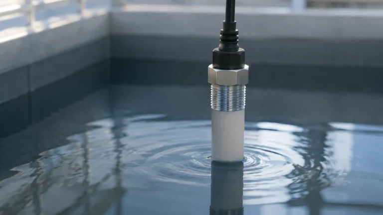
A specific application of pressure transduction is hydrostatic level measurement. By measuring the pressure at the bottom of a tank, the transmitter can calculate the liquid level based on the density of the fluid. For example, in a water tank, every 10 meters (approximately 32.8 feet) of water column exerts roughly 1 bar (14.5 psi) of pressure. Welk offers specialized hydrostatic transmitters designed for immersion in deep wells or open reservoirs.
Distinguishing Between Pressure Transducers and Transmitters
For procurement and engineering teams, choosing between a raw transducer and a fully integrated transmitter is a critical decision. The following table highlights the primary differences:
| Feature | Pressure Transducer | Pressure Transmitter |
| :— | :— | :— |
| Output Signal | Low-level (mV) | Standardized (4-20mA, 0-5V, Digital) |
| Transmission Distance | Short (typically < 10 meters) | Long (up to several kilometers) |
| EMI Resistance | Low | High |
| Cost | Lower | Higher |
| Complexity | Requires external signal conditioning | Plug-and-play with industrial controllers |
| Typical Use | OEM equipment, laboratory testing | Industrial process control, water treatment |
Key Evaluation Criteria for Industrial Applications
Selecting the right instrument requires a thorough analysis of the application's physical and chemical demands. When evaluating how a pressure transmitter will transduce signals in your facility, consider the following factors:
1. Pressure Type and Range
Determine if you need to measure gauge pressure (relative to atmospheric pressure), absolute pressure (relative to a vacuum), or differential pressure (the difference between two points). Ensure the transmitter’s calibrated range covers the maximum expected process pressure, including potential surges, without exceeding the burst pressure rating.
2. Media Compatibility
The wetted parts of the transmitter—the diaphragm and process connection—must be chemically compatible with the fluid. While 316L stainless steel is standard, aggressive chemicals may require Tantalum, Hastelloy, or PTFE coatings. For high-viscosity fluids or food-grade applications, flush-diaphragm designs prevent clogging and bacterial growth.
3. Accuracy and Stability
Accuracy is typically expressed as a percentage of the Full Scale (FS). For critical custody transfer or chemical dosing, high-precision transmitters (0.075% to 0.1% FS) are necessary. For general tank level monitoring, a standard accuracy of 0.5% FS is often sufficient. Long-term stability is also vital to reduce the frequency of re-calibration.
4. Environmental Conditions
Industrial environments often involve extreme temperatures, vibration, and moisture. Check the Ingress Protection (IP) rating; IP65 is standard for most indoor use, while IP68 is required for submersible hydrostatic sensors. If the transmitter is installed in a hazardous area (e.g., oil and gas), it must hold the appropriate explosion-proof or intrinsically safe certifications (ATEX/IECEx).
To explore specific technical specifications and product ranges, engineers should consult the Welk Main Page for a comprehensive overview of available measurement solutions.

Installation Considerations and Best Practices
The accuracy with which a pressure transmitter can transduce a signal is heavily influenced by how it is installed. Improper mounting can lead to zero-point shifts and premature failure.
* Mounting Position: Most transmitters are calibrated in a vertical position. If mounted horizontally, the weight of the internal fluid or the diaphragm itself may cause a small zero-offset, which must be corrected during commissioning.
* Impulse Lines: In steam or high-temperature gas applications, use impulse piping or siphons to create a liquid seal. This protects the sensor electronics from extreme heat. Ensure impulse lines are sloped to prevent gas pockets (in liquid lines) or condensate buildup (in gas lines).
* Electrical Connection: Use shielded, twisted-pair cabling for 4-20mA loops to minimize electrical noise. Ensure the cable entry is sealed properly to prevent moisture from entering the housing via capillary action.
* Venting: For gauge pressure transmitters, the reference side of the diaphragm must be vented to the atmosphere. Ensure the vent path is protected from water ingress and debris.
Limitations and Common Operational Risks
While modern pressure transmitters are highly reliable, certain conditions can compromise their ability to transduce pressure accurately:
1. Overpressure Events: Sudden pressure spikes (water hammer) can permanently deform the sensing diaphragm, leading to permanent calibration shifts or total failure. Installing snubbers can mitigate these risks.
2. Temperature Extremes: Although most transmitters include temperature compensation, operating outside the compensated temperature range will increase measurement error. In extreme cold, freezing of the process media in the impulse line can rupture the sensor.
3. Diaphragm Fatigue: In applications with high-frequency pressure pulsations, the diaphragm may eventually suffer from mechanical fatigue. In such cases, choosing a transmitter with a thicker diaphragm or using a chemical seal may be necessary.
4. Clogging: In wastewater or slurries, solids can accumulate against the diaphragm. Regular maintenance and the use of non-clogging flush designs are essential for these environments.
Frequently Asked Questions (FAQ)
Q: What is the difference between a 2-wire and a 4-wire pressure transmitter?
A: A 2-wire transmitter uses the same pair of wires for both power supply and the 4-20mA output signal, making it more efficient for industrial wiring. A 4-wire transmitter has separate pairs for power (often AC or high-voltage DC) and the output signal, which is common in older systems or devices requiring high power for displays and heaters.
Q: How often should a pressure transmitter be calibrated?
A: This depends on the criticality of the process and the stability of the instrument. Most industrial users perform a calibration check annually. However, for high-precision applications, a six-month interval may be required.
Q: Can I use a pressure transmitter to measure level in a pressurized tank?
A: Yes, but you must use a differential pressure (DP) transmitter. One port measures the total pressure at the bottom (liquid + headspace gas), and the other port measures the headspace pressure. The transmitter then subtracts the headspace pressure to provide the hydrostatic pressure of the liquid alone.
Q: Why is 4-20mA the standard signal for pressure transmitters?
A: The 4-20mA current loop is robust against electrical noise and signal loss over long distances. Additionally, the "live zero" of 4mA allows the system to distinguish between a zero-pressure reading and a broken wire (0mA).
By understanding the technical nuances of how these devices transduce physical force into data, engineers can better specify, install, and maintain the instrumentation necessary for safe and efficient industrial operations. For further assistance in selecting the correct instrument for your specific application, reviewing technical documentation on the Main Page is a recommended next step.