Optical Oxygen Analyzer
Optical Oxygen Analyzer
In the landscape of industrial process control and environmental monitoring, the optical oxygen analyzer has emerged as a cornerstone technology for measuring dissolved oxygen (DO) and gaseous oxygen levels. Unlike traditional electrochemical methods that rely on consumable electrolytes and permeable membranes, optical sensing utilizes the physics of luminescence quenching to provide highly stable, low-maintenance measurements. For engineers and procurement specialists in sectors such as water treatment, chemical processing, and industrial automation, understanding the nuances of this technology is essential for ensuring process efficiency and equipment longevity.
As industrial facilities move toward more autonomous and reliable monitoring systems, the optical oxygen analyzer represents a significant shift in how oxygen concentrations are tracked in real-time. This guide explores the fundamental principles, selection criteria, and practical implementation strategies for these instruments within a B2B context.
Measurement Principle: Luminescence Quenching
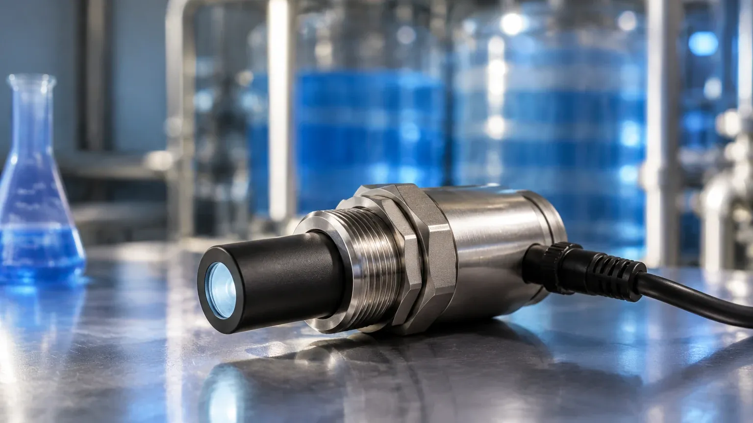
The operation of an optical oxygen analyzer is based on the principle of dynamic luminescence quenching. This process involves a sensor head equipped with a specialized sensing layer containing a luminophore (a luminescent dye) embedded in a gas-permeable matrix, typically silicone or a similar polymer.
The Excitation and Emission Cycle
1. Excitation: The instrument’s internal electronics trigger a light-emitting diode (LED)—usually emitting blue light—to shine onto the sensing layer.
2. Luminescence: The luminophore molecules absorb the energy from the blue light, reaching an excited state. As they return to their ground state, they emit light at a longer wavelength, typically in the red spectrum.
3. Quenching: If oxygen molecules are present in the medium (liquid or gas) being measured, they collide with the excited luminophore molecules. This collision facilitates a non-radiative energy transfer, effectively "quenching" the luminescence.
Signal Processing
The analyzer does not simply measure the brightness of the light. Instead, it measures the phase shift or the decay time of the luminescence. The more oxygen molecules present, the faster the luminescence is quenched and the shorter the decay time. Because the relationship between the oxygen partial pressure and the decay time is mathematically defined by the Stern-Volmer equation, the analyzer can calculate the oxygen concentration with high precision. This time-domain measurement is inherently more stable than intensity-based measurements, as it is less affected by LED aging or turbidity in the medium.
Comparative Analysis: Optical vs. Electrochemical
When evaluating an optical oxygen analyzer for industrial use, it is helpful to compare it against the legacy electrochemical (Galvanic or Polarographic) sensors.
| Feature | Optical Oxygen Analyzer | Electrochemical Sensor |
| :— | :— | :— |
| Maintenance | Low (Annual cap replacement) | High (Frequent electrolyte/membrane changes) |
| Flow Requirement | None (Zero flow independent) | Required (Oxygen is consumed during measurement) |
| Calibration Stability | High (Minimal drift over months) | Moderate (Requires frequent recalibration) |
| Response Time | Fast and consistent | Variable based on membrane thickness |
| Warm-up Time | Instantaneous | 15 to 60 minutes |
| Interference | Minimal (Not affected by H2S) | High (Sensitive to H2S, CO2, and pH) |
For many B2B applications, the lack of a flow requirement is the deciding factor. In stagnant water or low-flow chemical bypasses, electrochemical sensors will deplete the oxygen in the immediate vicinity of the membrane, leading to artificially low readings. The optical oxygen analyzer avoids this pitfall entirely, as it does not consume oxygen during the measurement process.
Key Evaluation Criteria for Industrial Procurement
Selecting the right optical oxygen analyzer requires a thorough assessment of the application environment. Technical buyers should focus on the following parameters:
1. Measurement Range and Accuracy
Most industrial optical analyzers are optimized for the range of 0 to 20 mg/L (or 0 to 200% saturation). However, for specialized applications like boiler feedwater monitoring, "trace level" sensors are required, capable of measuring in the parts-per-billion (ppb) range. Accuracy typically sits around ±0.1 mg/L or 1% of the reading, whichever is greater.
2. Physical and Chemical Compatibility
The sensor body is usually constructed from 316L stainless steel or high-performance plastics like PEEK. It is vital to ensure the sensing cap material is compatible with the process media. While optical sensors are immune to many chemical interferences that plague electrochemical probes, certain organic solvents or high concentrations of chlorine can degrade the luminophore matrix.
3. Temperature and Pressure Limits
Standard industrial optical sensors are rated for temperatures between -5°C and 50°C (23°F to 122°F). In applications involving Clean-in-Place (CIP) or Sterilization-in-Place (SIP) cycles, such as in the pharmaceutical or food industries, the sensor must be able to withstand temperatures up to 130°C (266°F). Pressure ratings typically range from 0 to 10 bar (0 to 145 psi).
4. Integration and Communication
Modern analyzers must integrate seamlessly into existing PLC or SCADA systems. Look for instruments offering:
* Analog Outputs: 4-20mA with HART protocol.
* Digital Communication: Modbus RTU (RS485), Profibus, or Foundation Fieldbus.
* Wireless Options: For remote environmental monitoring where cabling is cost-prohibitive.
For comprehensive system integration, engineers often Review product options and application support to ensure the selected instrumentation aligns with the broader automation architecture of the facility.
Application Scenarios and Process Integration
Wastewater Treatment
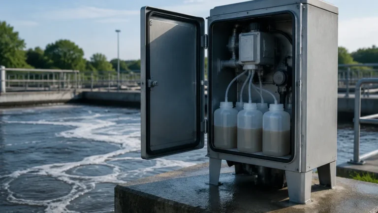
In activated sludge processes, maintaining the correct dissolved oxygen level in aeration basins is critical for the health of aerobic bacteria. Optical oxygen analyzers are preferred here because they resist fouling better than membrane-based sensors and do not require constant cleaning or electrolyte replenishment. Precise DO control can lead to energy savings of up to 30% by optimizing blower frequency.
Chemical and Petrochemical Processing
In chemical storage tanks and reactors, oxygen levels must often be kept at a minimum to prevent oxidation or explosive atmospheres (inerting). Optical analyzers are used for nitrogen blanketing verification. Since these sensors are not poisoned by hydrogen sulfide (H2S), they are ideal for oil and gas environments where sour gas may be present.
Aquaculture and Environmental Monitoring
For large-scale fish farming, oxygen is the most critical parameter for livestock survival. The stability of optical sensors allows for long-term deployment in remote locations without the need for weekly site visits for calibration.
Installation and Engineering Considerations
To maximize the lifespan and accuracy of an optical oxygen analyzer, proper installation is paramount.
1. Orientation: Sensors should ideally be installed at an angle (at least 15° from horizontal) to prevent air bubbles from becoming trapped on the sensing face, which would cause erratic high readings.
2. Flow Dynamics: While the sensor does not require flow to function, placing it in a location with representative process flow ensures that the measurement reflects the actual state of the bulk medium and prevents the buildup of sediment or bio-film.
3. Cable Management: In industrial environments, signal cables should be shielded and kept away from high-voltage power lines to prevent electromagnetic interference (EMI), although optical signals are generally more robust than the low-current signals of electrochemical probes.
4. Submersion Depth: For open-tank applications, ensure the sensor is submerged deep enough to avoid the effects of surface turbulence and atmospheric oxygen exchange, typically at least 300 mm (approx. 12 inches) below the surface.
Potential Risks and Technical Limitations
Despite their advantages, optical oxygen analyzers are not without limitations:
* Photobleaching: Over time, the constant exposure to excitation light can degrade the luminophore dye. While modern algorithms compensate for this, the sensing cap will eventually need replacement (typically every 12 to 24 months).
* Temperature Sensitivity: The quenching process is temperature-dependent. High-quality analyzers include an integrated NTC or PT1000 temperature sensor to provide automatic compensation. If the temperature sensor fails, the oxygen reading will be inaccurate.
* Ambient Light Interference: While most caps are opaque to external light, extremely intense direct sunlight can sometimes interfere with the photodetector. Installing a simple sunshade or orienting the sensor away from direct light can mitigate this.
Practical Selection Table for Industrial Use
| Application | Recommended Sensor Material | Range Requirement | Key Feature to Prioritize |
| :— | :— | :— | :— |
| Wastewater Aeration | PVC or Stainless Steel | 0-20 mg/L | Anti-fouling coating |
| Boiler Feedwater | 316L Stainless Steel | 0-2000 μg/L (Trace) | High sensitivity/Low drift |
| Chemical Storage | Hastelloy or PEEK | 0-25% O2 (Gas) | Explosion-proof (ATEX) rating |
| Fermentation | Electropolished SS | 0-100% Saturation | CIP/SIP compatibility |
Frequently Asked Questions (FAQ)
Q: How often does an optical oxygen analyzer need calibration?
A: In most stable industrial environments, optical sensors can maintain calibration for 6 to 12 months. However, for regulatory compliance or critical safety processes, a quarterly verification is recommended.
Q: Can the sensor be used in pressurized pipes?
A: Yes, most industrial optical oxygen analyzers are designed to handle pressures up to 10 bar. It is important to use a proper process connection, such as a NPT thread or a flange, to ensure a leak-proof seal.
Q: Is the sensing cap a consumable item?
A: Yes. The sensing cap contains the luminophore and is considered a wear part. Depending on the intensity of use and the harshness of the environment, it typically lasts between one and two years. Replacing the cap is a simple process that usually takes less than five minutes.
Q: Does turbidity affect the measurement?
A: Generally, no. Because the analyzer measures the phase shift of the light rather than the intensity, suspended solids (turbidity) do not interfere with the oxygen calculation unless the solids physically block the sensing face.
Conclusion
The optical oxygen analyzer has redefined the standards for oxygen measurement in the B2B industrial sector. By leveraging the stability of luminescence quenching, these instruments provide a reliable, low-maintenance solution that outperforms traditional electrochemical methods in almost every metric. When integrated correctly—considering the chemical environment, physical installation, and data communication needs—an optical oxygen analyzer becomes an invaluable asset for process optimization and environmental stewardship.
For engineers seeking to upgrade their current measurement systems or design new process loops, visiting the Main Page of a dedicated instrumentation provider can offer further insights into the specific hardware configurations available for diverse industrial needs.