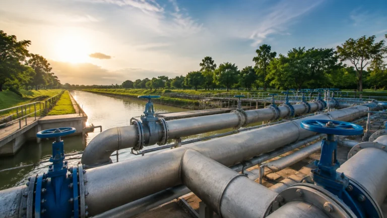
People for Process Automation
People for Process Automation
In the modern industrial landscape, the phrase "people for process automation" represents the critical intersection between advanced instrumentation and human engineering expertise. While hardware like radar level meters and ultrasonic sensors provides the data, it is the specialized knowledge of engineers and technicians that ensures these systems are integrated effectively into complex workflows. For industries ranging from water treatment to chemical processing, automation is not merely about installing a device; it is about the collaborative effort to solve measurement challenges through precise selection, installation, and maintenance.
Reliable level measurement is a cornerstone of process safety and efficiency. To achieve this, stakeholders must understand the underlying physics of measurement technologies and how human intervention optimizes these tools for specific environmental conditions. This guide examines the core principles of level measurement and the role of expert guidance in achieving seamless process automation.
Core Principles of Level Measurement
Before selecting an instrument, it is essential to understand the measurement principles that drive modern automation. Each technology interacts differently with the process media and the vessel environment.
1. Radar Level Measurement (ToF)
Radar level meters operate on the Time-of-Flight (ToF) principle. The device emits high-frequency microwave pulses (typically in the GHz range) that travel at the speed of light. When these pulses hit the surface of the medium, they are reflected back to the sensor. The distance is calculated based on the time interval between transmission and reception.
* Non-Contact Radar: Ideal for corrosive or high-temperature liquids as the sensor does not touch the media.
* Guided Wave Radar (GWR): Uses a probe to guide the signal, making it highly effective for low dielectric constant (εr) liquids or applications with heavy foam and turbulence.
2. Ultrasonic Level Sensors
Ultrasonic sensors also use the ToF principle but utilize sound waves instead of electromagnetic waves. A transducer emits an ultrasonic pulse that reflects off the surface of the material. Because sound velocity is affected by air temperature, these sensors usually include integrated temperature compensation to maintain accuracy.
3. Hydrostatic Pressure Measurement
Hydrostatic transmitters measure the pressure exerted by a liquid column at a specific point. The level ($H$) is calculated using the formula $P = ρ × g × H$, where $P$ is pressure, $ρ$ is the density of the liquid, and $g$ is the gravitational constant. This method is highly reliable for vented tanks with stable liquid densities.
4. Magnetic Level Gauges
Operating on the principle of buoyancy and magnetic coupling, these gauges use a float containing a permanent magnet. As the float rises and falls with the liquid level, it actuate a series of bi-color flaps or a transmitter outside the chamber. This provides a clear visual indication without requiring power, often used as a redundant safety system.
The Human Element: Expertise in Technology Selection
Automation systems fail most frequently not because of hardware defects, but due to improper specification. This is where the "people for process automation" become vital. Engineers must evaluate several variables that a datasheet alone cannot resolve.
Key Evaluation Criteria
* Media Characteristics: Is the liquid viscous, corrosive, or prone to crystallization? Does it have a low dielectric constant that might weaken radar reflections?
* Vessel Geometry: Internal obstructions like agitators, heating coils, or baffles can create "false echoes" for acoustic and electromagnetic sensors.
* Process Conditions: Extreme pressures (exceeding 40 bar) or temperatures (above 200°C) require specific housing materials and cooling elements.
* Accuracy Requirements: Custody transfer applications require millimeter-level precision, whereas simple pump control may only require ±1% accuracy.
To explore specific hardware configurations that meet these criteria, engineers often refer to the Main Page of technical catalogs to compare model specifications against process demands.
Practical Selection Table
The following table provides a general guideline for matching technology to common industrial applications.
| Technology | Best For | Limitations | Typical Accuracy |
| :— | :— | :— | :— |
| Non-Contact Radar | Corrosive liquids, high temps, large silos | Low dielectric media, heavy foam | ±2 mm to ±5 mm |
| Guided Wave Radar | Small tanks, low εr liquids, interface measurement | Physical contact with media, buildup on probe | ±2 mm |
| Ultrasonic | Water treatment, open channels, sumps | Vacuum, high dust, steam/vapor | ±0.25% of range |
| Hydrostatic | Deep wells, vented tanks, constant density | Changing density, pressurized tanks | ±0.1% to ±0.5% |
| Magnetic Gauge | High-pressure boilers, visual monitoring | High viscosity, magnetic particles | ±5 mm to ±10 mm |
Engineering Installation Considerations
Proper installation is the bridge between a theoretical measurement and a functional process loop. The "people for process automation"—the field technicians and installers—must adhere to strict geometric constraints to ensure signal integrity.
1. Nozzle Height and Diameter: For radar and ultrasonic sensors, the nozzle should be as short and wide as possible to prevent the signal from reflecting off the nozzle walls before reaching the tank interior.
2. The "Dead Zone" (Blocking Distance): Every ToF sensor has a minimum distance near the transducer where it cannot measure. If the liquid enters this zone, the reading becomes erratic. Designers must account for this when calculating maximum tank fill levels.
3. Mounting Position: Sensors should generally be mounted at 1/6th to 1/4th of the tank diameter from the wall. Mounting too close to the wall causes interference, while mounting in the center of a domed tank can cause multiple reflections that confuse the signal processor.
4. Agitator Interference: If an agitator is present, the sensor should be positioned such that the signal beam does not strike the blades. Advanced software can "map out" these static reflections, but physical avoidance is always the primary strategy.

Limitations and Common Risks
Even the most advanced automation systems have boundaries. Recognizing these limitations is essential for maintaining a safe and productive environment.
* Foam and Turbulence: Heavy foam can absorb ultrasonic and radar signals, leading to a "loss of echo." In these cases, guided wave radar or hydrostatic transmitters are often preferred.
* Vapor and Condensation: High concentrations of steam can attenuate ultrasonic signals. For radar, condensation on the antenna can cause signal drift if the antenna does not have a specialized PTFE (Polytetrafluoroethylene) drip-off design.
* Build-up and Coating: In wastewater or chemical mixing, material may coat the sensor. While some radar units can penetrate thin coatings, magnetic gauges and pressure diaphragms may fail if the build-up prevents mechanical movement or blocks the pressure port.
* Environmental Noise: Electrical interference or mechanical vibrations can introduce noise into 4-20mA loops. Using shielded cables and proper grounding is a fundamental requirement for the people for process automation responsible for wiring.
Frequently Asked Questions (FAQ)
Q: Can I use one level meter for all my tanks to simplify inventory?
A: While some radar units are versatile, a "one size fits all" approach usually leads to over-spending on simple tanks or under-performing on difficult ones. It is better to standardize on a few technologies (e.g., radar for chemicals, hydrostatic for water) rather than a single model.
Q: How often should level transmitters be calibrated?
A: This depends on the industry. In regulated chemical or pharmaceutical sectors, annual calibration is standard. For general water monitoring, a verification check every two years may suffice. Always follow the manufacturer's guidelines found on the Main Page of the product manual.
Q: What is the difference between a level switch and a level transmitter?
A: A level switch provides point-level detection (e.g., "tank is full" or "tank is empty") and is used for overfill protection. A level transmitter provides continuous measurement (e.g., "tank is at 45%") and is used for process control and inventory management.
Q: Does temperature affect radar measurement?
A: Unlike ultrasonic measurement, radar is largely unaffected by air temperature because electromagnetic waves do not require a medium to travel. However, the electronics and housing must still be rated for the ambient and process temperatures.
Conclusion
The success of industrial operations depends on more than just high-quality hardware; it relies on the expertise of the people for process automation who design, install, and maintain these systems. By understanding the physics of measurement—whether through the precision of radar or the reliability of hydrostatic pressure—and applying rigorous engineering standards during installation, facilities can achieve higher levels of safety and efficiency. For those seeking to optimize their processes, consulting detailed technical resources and product specifications is the necessary next step in ensuring that the chosen technology aligns with the reality of the plant floor.