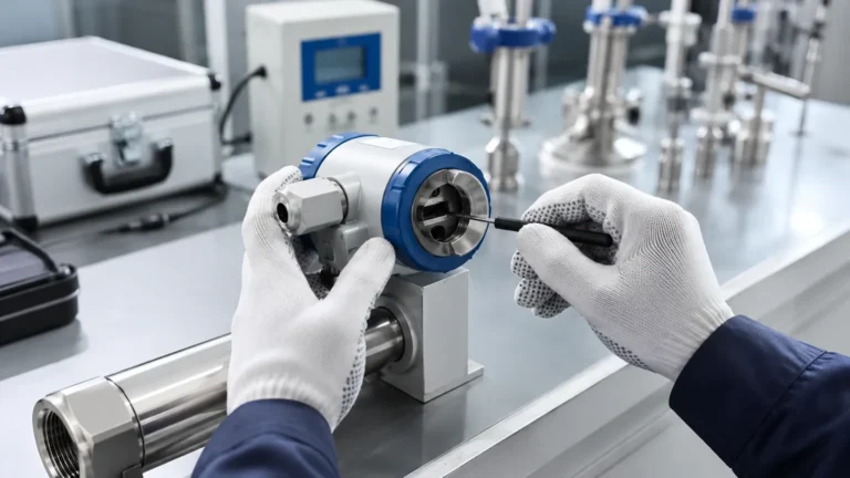
Rtd Temperature Sensors
Rtd Temperature Sensors
In the landscape of industrial process control, accuracy and stability are the primary benchmarks for instrumentation. Resistance Temperature Detectors, commonly known as RTD temperature sensors, have established themselves as the industry standard for precision temperature measurement. Unlike thermocouples, which rely on the Seebeck effect between dissimilar metals, RTDs operate on the principle that the electrical resistance of a metal changes in a predictable and repeatable manner as its temperature fluctuates.
For professionals managing complex systems—ranging from chemical processing to water treatment—understanding the nuances of RTD technology is essential. This guide explores the fundamental principles, wiring configurations, and the critical role these sensors play in ensuring the accuracy of level measurement systems.
Understanding the Principles of RTD Temperature Sensors
The operation of an RTD is based on the linear relationship between the electrical resistance of a conductor and its temperature. Most metals exhibit an increase in resistance as they get hotter, a characteristic known as a positive temperature coefficient (PTC).
The Physics of Resistance Change
At a molecular level, as the temperature of a metal increases, the thermal vibrations of the atoms within the crystal lattice increase. These vibrations impede the flow of electrons (the electrical current), thereby increasing the resistance. For industrial applications, platinum is the most widely used material because it offers a highly linear resistance-to-temperature relationship, excellent chemical stability, and a wide operating range.
The Callendar-Van Dusen Equation
The relationship between resistance ($R$) and temperature ($t$) for a platinum RTD is defined by the Callendar-Van Dusen equation. For temperatures above 0°C, the formula is generally expressed as:
$$R_t = R_0 [1 + At + Bt^2]$$
Where:
* $R_t$ is the resistance at temperature $t$.
* $R_0$ is the resistance at 0°C (typically 100 Ω for Pt100 sensors).
* $A$ and $B$ are constants derived from the properties of the platinum used.
By measuring the resistance with high precision, a transmitter or controller can calculate the exact temperature of the process medium.
Materials and Construction of Resistance Elements
While platinum is the gold standard, other metals are used depending on the specific requirements of the application. The choice of material affects the sensor's sensitivity, range, and cost.
1. Platinum (Pt): The most common choice (e.g., Pt100, Pt1000). It covers a range from -200°C to 850°C. It is highly stable and resistant to contamination.
2. Nickel (Ni): Offers a higher resistance change per degree than platinum but has a limited temperature range (typically up to 300°C) and is less linear.
3. Copper (Cu): Known for its excellent linearity, but it has a narrow temperature range (-200°C to 150°C) and is susceptible to oxidation.
RTD elements are typically manufactured in two forms:
* Wire-Wound Elements: A fine platinum wire is coiled around a ceramic or glass core. These are highly accurate and stable but can be sensitive to high-vibration environments.
* Thin-Film Elements: A thin layer of platinum is deposited onto a ceramic substrate and then encapsulated. These are more rugged, faster-responding, and cost-effective, making them suitable for many industrial automation tasks.
Wiring Configurations: 2, 3, and 4-Wire Systems
One of the most critical factors in RTD accuracy is the management of lead wire resistance. Since the sensor measures small changes in Ohms, the resistance of the wires connecting the sensor to the control system can introduce significant errors.
2-Wire Configuration
This is the simplest setup, where two wires provide the excitation current and measure the voltage. However, the lead wire resistance is added directly to the sensor's resistance, leading to a permanent positive offset in temperature readings. This configuration is only recommended for applications where the leads are very short or high accuracy is not required.
3-Wire Configuration
The 3-wire configuration is the industrial standard. It uses a third wire to measure the lead resistance and subtract it from the total measurement. This assumes that all three wires have the same resistance and are at the same temperature. It provides a balance between cost and accuracy, making it the default choice for most PLC and DCS inputs.
4-Wire Configuration
For laboratory-grade precision or applications where lead wire resistance varies significantly, a 4-wire (Kelvin) connection is used. Two wires carry the excitation current, while the other two measure the voltage drop across the RTD element. Because the voltage measurement circuit has very high impedance, virtually no current flows through the sense leads, eliminating lead wire resistance from the calculation entirely.
The Role of RTD Sensors in Level Measurement Accuracy
In industrial environments, temperature and level measurement are often interdependent. Many level measurement technologies require temperature compensation to maintain their specified accuracy. This is where rtd temperature sensors become integral to the broader instrumentation strategy.
Hydrostatic Level Measurement
Hydrostatic level transmitters determine the liquid level by measuring the pressure exerted by the liquid column. The formula used is $P = ρgh$ (Pressure = Density × Gravity × Height). Because the density ($ρ$) of a liquid changes with temperature, a hydrostatic sensor without temperature compensation will report an incorrect level as the process warms or cools. Integrating an RTD allows the system to adjust the density calculation in real-time.
Ultrasonic and Radar Level Meters
Ultrasonic level sensors measure the time-of-flight of a sound wave. The speed of sound in air (or gas) is highly dependent on temperature, changing by approximately 0.6 m/s for every degree Celsius. Without an RTD to monitor the vapor space temperature, the level reading could drift by several percentage points. Even in radar level measurement, while less affected by temperature than ultrasonic, extreme temperature fluctuations can affect the dielectric constant of certain materials or the physical integrity of the mounting, necessitating temperature monitoring.
For engineers designing these systems, reviewing comprehensive product options and application support on the Main Page of an industrial manufacturer like Welk is a vital step in ensuring sensor compatibility.
Selection Criteria for Industrial RTDs
Choosing the right RTD involves more than just selecting a Pt100 element. Engineers must consider the physical and chemical environment of the process.
| Criteria | Description | Recommendation |
| :— | :— | :— |
| Temperature Range | The minimum and maximum expected process temperatures. | Use Platinum for wide ranges; Thin-film for vibration. |
| Accuracy Class | Defined by IEC 60751 (Class AA, A, B). | Class A is standard for process control (±0.15°C at 0°C). |
| Sheath Material | The outer protective tube (316 Stainless Steel, Inconel, etc.). | 316SS for water/general use; Hastelloy for corrosive chemicals. |
| Response Time | How quickly the sensor reacts to a change in temperature. | Smaller diameter probes respond faster but are less robust. |
| Connection Type | Threaded, flanged, or sanitary (tri-clamp). | Match the existing vessel or pipework standards. |
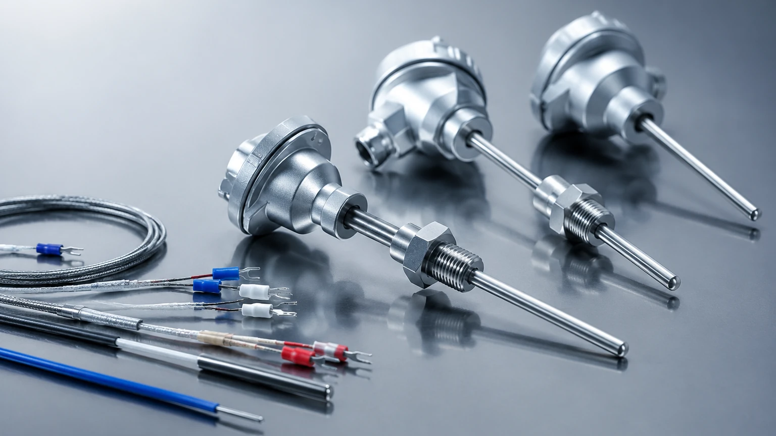
Installation Best Practices and Considerations
Proper installation is paramount to preventing measurement errors such as stem conduction or self-heating.
1. Thermowells: In high-pressure or high-velocity flows, RTDs should be installed in thermowells. This allows for the removal of the sensor without breaking the process seal and protects the element from mechanical damage. However, thermowells increase the response time.
2. Immersion Depth: To avoid "stem conduction" error (where heat travels along the sensor sheath to the outside air), the sensor should be immersed to a depth of at least 10 times the diameter of the protection tube. In a 6 mm probe, this means a minimum immersion of 60 mm.
3. Self-Heating: RTDs require an excitation current to operate. This current generates a small amount of heat within the element. To minimize this, the excitation current should be kept low (typically 1 mA or less).
4. Vibration: In applications with high mechanical vibration, such as near pumps or compressors, thin-film RTDs or specialized vibration-resistant wire-wound elements should be used to prevent fatigue failure of the platinum wire.
Limitations and Common Challenges
While highly accurate, RTD temperature sensors are not suitable for every application. Their primary limitations include:
* Cost: RTDs are generally more expensive than thermocouples due to the cost of platinum and the complexity of construction.
* Fragility: Despite modern thin-film technology, the ceramic substrates and fine wires can be damaged by extreme shock or vibration if not properly housed.
* Temperature Ceiling: RTDs are typically limited to 850°C, whereas certain thermocouples can measure up to 1700°C.
* Slow Response: Compared to fine-wire thermocouples, the mass of the RTD element and its protective sheath results in a slower response to rapid temperature transients.
Frequently Asked Questions (FAQ)
Q: What is the difference between Pt100 and Pt1000?
A: A Pt100 sensor has a resistance of 100 Ω at 0°C, while a Pt1000 has 1000 Ω. Pt1000 sensors are often used in battery-powered applications because the higher resistance allows for lower current consumption, and they are less sensitive to lead wire resistance in 2-wire setups.
Q: How often should RTD sensors be calibrated?
A: In critical process industries, annual calibration is standard. However, if the sensor is subjected to mechanical shock or temperatures at the extreme end of its range, more frequent checks are advisable to monitor for "drift."
Q: Can I use a 3-wire RTD with a 2-wire transmitter?
A: Yes, you can simply leave the third wire disconnected or jump it at the terminal, but you will lose the lead wire compensation benefits, effectively turning it into a 2-wire system.
Q: Why is my RTD reading higher than the actual temperature?
A: This is often caused by self-heating (too much excitation current) or a positive offset caused by lead wire resistance in a 2-wire configuration.
Conclusion
RTD temperature sensors remain a cornerstone of industrial instrumentation due to their unmatched stability and repeatability. When integrated correctly—particularly in synergy with level measurement technologies—they provide the data necessary for safe, efficient, and accurate process control. By selecting the appropriate wiring configuration, material, and installation method, engineers can ensure long-term reliability even in the most demanding industrial environments. For further technical specifications and to explore integrated level and temperature solutions, professionals are encouraged to consult the Main Page of established manufacturers to find the right fit for their specific application requirements.