What Is a Safety Instrumented System
What Is a Safety Instrumented System
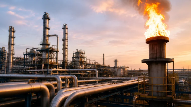
In high-risk industrial environments, such as chemical processing, oil and gas refining, and large-scale water treatment, the prevention of catastrophic failures is a primary engineering objective. Central to this objective is the implementation of a Safety Instrumented System (SIS). Understanding what is a safety instrumented system requires a deep look into how automated safeguards operate independently of standard process controls to protect personnel, the environment, and capital assets.
A Safety Instrumented System is a distinct set of hardware and software controls designed to monitor a specific process and, upon detecting an unsafe condition, automatically bring the process to a safe state. It acts as a secondary layer of protection, sitting above the Basic Process Control System (BPCS). While the BPCS manages day-to-day operations—maintaining levels, pressures, and temperatures within a normal range—the SIS remains dormant until a critical threshold is breached.
The Core Architecture of an SIS
To fully grasp what is a safety instrumented system, one must understand its three fundamental components. These components work in a loop, often referred to as a Safety Instrumented Function (SIF):
1. Sensors: These are the "eyes" of the system. In level measurement applications, these may include radar level meters, ultrasonic sensors, or point-level switches. They monitor process variables and report data to the logic solver.
2. Logic Solvers: This is the "brain," typically a Safety PLC (Programmable Logic Controller). It receives signals from the sensors, evaluates them against pre-programmed safety limits, and decides if action is necessary.
3. Final Control Elements: These are the "hands" that execute the safety action. Common examples include emergency shutdown valves (ESV), solenoid valves, or circuit breakers that cut power to a pump.
For an SIS to be effective, it must be independent of the BPCS. If the sensor used for regular level control fails, the SIS must have its own dedicated sensor to detect the resulting overfill condition.
Measurement Principles in Safety Applications
Before selecting instrumentation for an SIS, engineers must evaluate the underlying measurement principles. Reliability in a safety context depends on how well the technology handles the specific physical properties of the medium. For more information on specific hardware configurations, you can Review product options and application support on our Main Page.
Radar Level Measurement (ToF)
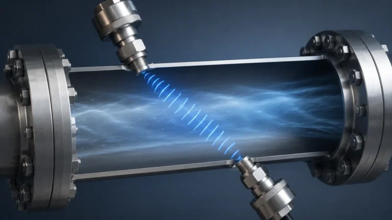
Radar level meters operate on the Time-of-Flight (ToF) principle. The device emits high-frequency microwave pulses that travel at the speed of light. When these pulses hit the surface of the liquid or solid, they are reflected back to the sensor. The distance is calculated based on the time interval between emission and reception.
In an SIS, radar is often preferred because it is non-contact. It is not affected by changes in density, pressure, or temperature, making it highly reliable for critical high-level alarms in volatile chemical tanks.
Ultrasonic Level Measurement
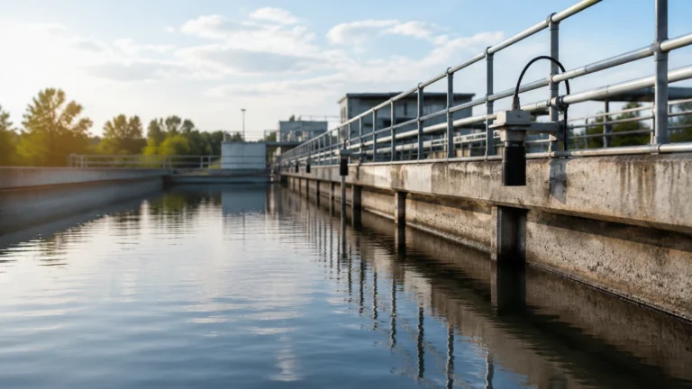
Similar to radar, ultrasonic sensors use ToF but utilize sound waves instead of electromagnetic waves. A transducer emits an ultrasonic pulse (typically in the 20 kHz to 200 kHz range), which reflects off the target. While cost-effective, ultrasonic measurement is sensitive to air temperature changes and heavy foam, which can attenuate the sound signal. In safety systems, they are generally reserved for stable, ambient-temperature water treatment applications.
Hydrostatic Pressure Measurement
Hydrostatic transmitters measure the pressure exerted by a liquid column. The principle is based on the formula $P = \rho gh$, where $P$ is pressure, $\rho$ is density, $g$ is gravity, and $h$ is the height of the liquid. For safety systems, hydrostatic sensors are robust but require the liquid density to remain constant to maintain accuracy. They are frequently used in deep well or open tank safety monitoring.
Point Level Switches
Unlike continuous transmitters, switches (such as tuning fork or magnetic float switches) provide a binary output (on/off). In a safety loop, a tuning fork switch vibrates at a specific frequency. When the liquid covers the fork, the frequency changes, triggering the logic solver. These are often used as the final "high-high" level trip because of their mechanical simplicity and high reliability.
Safety Integrity Levels (SIL) Explained
When discussing what is a safety instrumented system, the term "SIL" (Safety Integrity Level) is unavoidable. SIL is a measure of the performance required for a Safety Instrumented Function. It is defined by the international standard IEC 61508 and IEC 61511.
There are four SIL levels, with SIL 4 being the highest level of safety integrity. Most industrial process applications fall within SIL 1 to SIL 3. The level is determined by the Probability of Failure on Demand (PFD):
| SIL Level | Probability of Failure on Demand (PFDavg) | Risk Reduction Factor (RRF) |
| :— | :— | :— |
| SIL 1 | $\ge 10^{-2}$ to $< 10^{-1}$ | 10 to 100 |
| SIL 2 | $\ge 10^{-3}$ to $< 10^{-2}$ | 100 to 1,000 |
| SIL 3 | $\ge 10^{-4}$ to $< 10^{-3}$ | 1,000 to 10,000 |
| SIL 4 | $\ge 10^{-5}$ to $< 10^{-4}$ | 10,000 to 100,000 |
For a level meter to be used in a SIL 2 or SIL 3 loop, it must be certified by a third party (like exida or TÜV) or have a proven-in-use track record that meets the rigorous statistical requirements for reliability.
Selection Criteria for SIS Level Instrumentation
Choosing the right instrument for a safety loop involves more than just measuring range. Engineers must consider the "Safety Manual" provided by the manufacturer, which outlines the device's failure rates (Safe Detected, Safe Undetected, Dangerous Detected, and Dangerous Undetected).
Practical Selection Table
| Technology | Suitability for SIS | Primary Advantage | Main Limitation |
| :— | :— | :— | :— |
| Guided Wave Radar | High (SIL 2/3) | Immune to vapor/dust | Contact with medium required |
| Non-Contact Radar | High (SIL 2/3) | No moving parts; hygienic | High initial cost |
| Tuning Fork Switch | Very High (SIL 3) | Independent of fluid properties | Point level only |
| Hydrostatic | Moderate (SIL 1/2) | Simple installation | Density dependent |
| Magnetic Gauge | Moderate (SIL 1/2) | Visual confirmation | Moving parts (float) can jam |

Installation and Redundancy Considerations
Even the most reliable sensor can fail. To achieve higher SIL ratings, SIS designs often employ redundancy. This is referred to as Hardware Fault Tolerance (HFT).
* 1oo1 (One out of One): A single sensor. If it fails, the safety function is lost.
* 1oo2 (One out of Two): Two sensors are installed. If either sensor detects a high level, the system trips. This increases safety but also increases the chance of a "nuisance trip" (false alarm).
* 2oo3 (Two out of Three): Three sensors are installed. The system trips only if at least two sensors agree. This provides a balance between high safety integrity and high process availability.
Installation Best Practices
* Separation: Ensure the SIS sensor is physically separated from the BPCS sensor. They should not share the same process tapping if possible, to avoid common-cause failures (e.g., a single blocked nozzle affecting both sensors).
* Stilling Wells: For radar or ultrasonic sensors in turbulent tanks, use a stilling well (typically 50 mm to 100 mm [2" to 4"] diameter) to provide a smooth surface for measurement.
* Environmental Protection: Ensure the housing is rated for the environment (e.g., IP67 or NEMA 4X) and that cable entries are sealed to prevent moisture ingress, which is a leading cause of electronic failure in safety systems.
Limitations and Maintenance
A common misconception regarding what is a safety instrumented system is that once installed, it provides permanent protection. In reality, an SIS requires a lifecycle management approach.
The Proof Test
Every SIF must undergo periodic "Proof Testing." This is a manual test to detect "Dangerous Undetected" failures that the system's internal diagnostics cannot see. For a level switch, this might involve physically raising the liquid level to ensure the switch trips. For a radar meter, it might involve a comprehensive check of the electronics and a verification of the distance reading against a manual tape measure.
Limitations
* Bypass Risks: During maintenance, safety loops are often bypassed. If the bypass is not removed after maintenance, the SIS is useless.
* Common Cause Failure (CCF): If you use three identical sensors from the same batch, a design flaw or a specific environmental condition (like extreme cold) might cause all three to fail simultaneously. Using diverse technologies (e.g., one radar and one tuning fork) can mitigate this risk.
Frequently Asked Questions (FAQs)
Q: Can I use a standard level transmitter in an SIS?
A: Only if it has the necessary failure rate data (FMEDA report) and meets the SIL requirements of the specific SIF. Many Welk industrial-grade sensors are designed with these safety requirements in mind.
Q: What is the difference between a trip and a transmitter?
A: A transmitter provides a continuous signal (e.g., 4-20mA or HART) representing the level. A trip (or switch) provides a simple contact closure at a specific point. Modern SIS designs often use a combination of both for diversity.
Q: How often should I proof test my SIS level sensors?
A: The proof test interval is determined during the design phase to ensure the PFDavg remains within the required SIL range. Common intervals are 12, 24, or 60 months.
Q: Does an SIS prevent all accidents?
A: No. An SIS reduces risk to a "tolerable level." It is one of many layers, including mechanical relief valves, dikes/bunds, and emergency response procedures.
Conclusion
Understanding what is a safety instrumented system is vital for any engineer working in the process industries. By combining reliable level measurement technologies—such as Welk's radar and ultrasonic sensors—with rigorous logic solvers and final control elements, facilities can significantly reduce the probability of environmental disasters and equipment damage. When selecting instrumentation, always prioritize devices with clear safety documentation and a proven track record in your specific application environment. For a comprehensive look at suitable instrumentation, Review product options and application support to ensure your safety loops are built on a foundation of accuracy and reliability.