Flow Measurement Device
Flow Measurement Device
In industrial process control, the ability to accurately quantify the movement of liquids, gases, and steam is fundamental to operational efficiency, safety, and fiscal accountability. A flow measurement device is an instrument used to measure the linear, nonlinear, mass, or volumetric flow rate of a fluid. While often discussed alongside level measurement, flow instrumentation requires a distinct understanding of fluid dynamics and mechanical principles to ensure the selected technology matches the specific requirements of the application.
Selecting the appropriate flow measurement device involves evaluating the physical properties of the fluid, the dynamics of the piping system, and the required precision for the process. This guide provides a technical overview of measurement principles, selection criteria, and installation best practices for engineering professionals.
Fundamental Principles of Flow Measurement
Before selecting a device, it is essential to understand the physics governing different measurement technologies. Flow meters are generally categorized by the principle they use to derive the flow rate.
Differential Pressure (DP) Flow Meters
Differential pressure meters operate on Bernoulli’s principle, which states that as the speed of a moving fluid increases, the pressure within the fluid decreases. By placing a restriction in the pipe—such as an orifice plate, Venturi tube, or flow nozzle—a pressure drop is created. The square root of this pressure differential is proportional to the flow rate. DP meters are robust and well-understood but can cause permanent pressure loss in the system.
Electromagnetic Flow Meters (Magmeters)
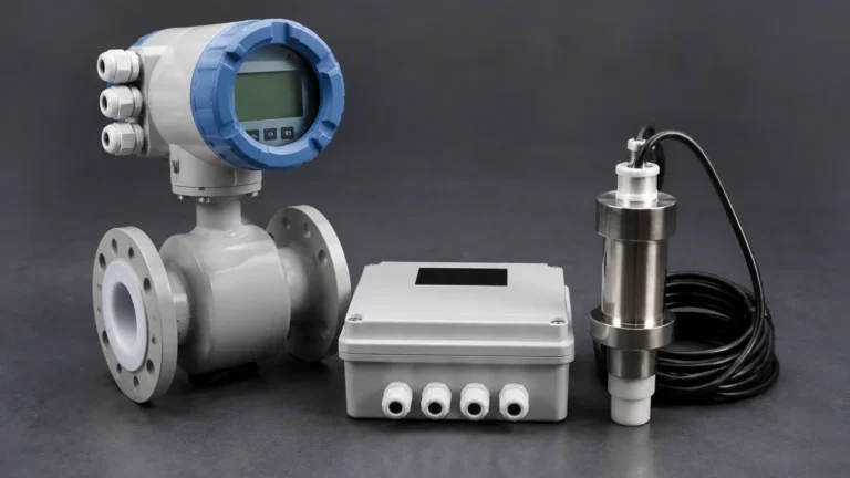
Magmeters function based on Faraday’s Law of Electromagnetic Induction. When a conductive liquid flows through a magnetic field generated by the meter, it produces a voltage proportional to the velocity of the fluid. Because they have no moving parts and offer no obstruction to the flow, they are ideal for slurries and corrosive liquids, provided the medium meets a minimum conductivity threshold (typically >5 μS/cm).
Ultrasonic Flow Meters
Ultrasonic devices use sound waves to determine fluid velocity. There are two primary types:
1. Transit-time: Measures the time difference between signals sent upstream and downstream. This is best for clean liquids.
2. Doppler: Measures the frequency shift of signals reflected off bubbles or particles in the flow. This is suitable for aerated or dirty liquids.
These devices are often available in "clamp-on" configurations, allowing for measurement without cutting into the pipework.
Vortex Flow Meters
Vortex meters utilize the principle of von Kármán vortices. As fluid passes a "shedder bar" placed in the flow stream, alternating vortices are created. The frequency of these vortices is directly proportional to the fluid velocity. These are highly versatile and commonly used for steam, gases, and low-viscosity liquids.
Coriolis Mass Flow Meters
Unlike volumetric meters, Coriolis meters measure mass flow directly. As fluid moves through a vibrating tube, it induces a twist in the tube due to Coriolis forces. The amount of twist is proportional to the mass flow rate. These are among the most accurate flow measurement devices available and are independent of changes in fluid density, pressure, or temperature.
Selecting the Right Flow Measurement Device
Choosing the correct instrument requires a systematic comparison of the application's constraints against the capabilities of the technology. The following table outlines the typical performance characteristics of common flow measurement devices.
Flow Meter Selection Matrix
| Technology | Typical Accuracy | Fluid Type | Pressure Drop | Maintenance Level |
| :— | :— | :— | :— | :— |
| Differential Pressure | ±0.5% to ±2% | Liquid, Gas, Steam | Medium to High | Moderate |
| Electromagnetic | ±0.2% to ±0.5% | Conductive Liquids | Negligible | Low |
| Ultrasonic | ±0.5% to ±1% | Clean/Dirty Liquids | None | Low |
| Vortex | ±0.7% to ±1% | Liquid, Gas, Steam | Medium | Low |
| Coriolis | ±0.1% | Most Fluids | Medium | Low |
| Turbine | ±0.25% to ±0.5% | Clean Liquids/Gases | High | High |
When evaluating these options, engineers must also consider the Main Page of the system's requirements, including total cost of ownership and integration with existing level measurement instruments. For example, in open channel applications, flow is often calculated by measuring the head level using ultrasonic or radar level sensors, illustrating the close relationship between level and flow instrumentation.
Installation Considerations and Best Practices
The performance of a flow measurement device is heavily dependent on its installation environment. Even the most accurate meter will provide unreliable data if installed incorrectly.
Straight Pipe Requirements
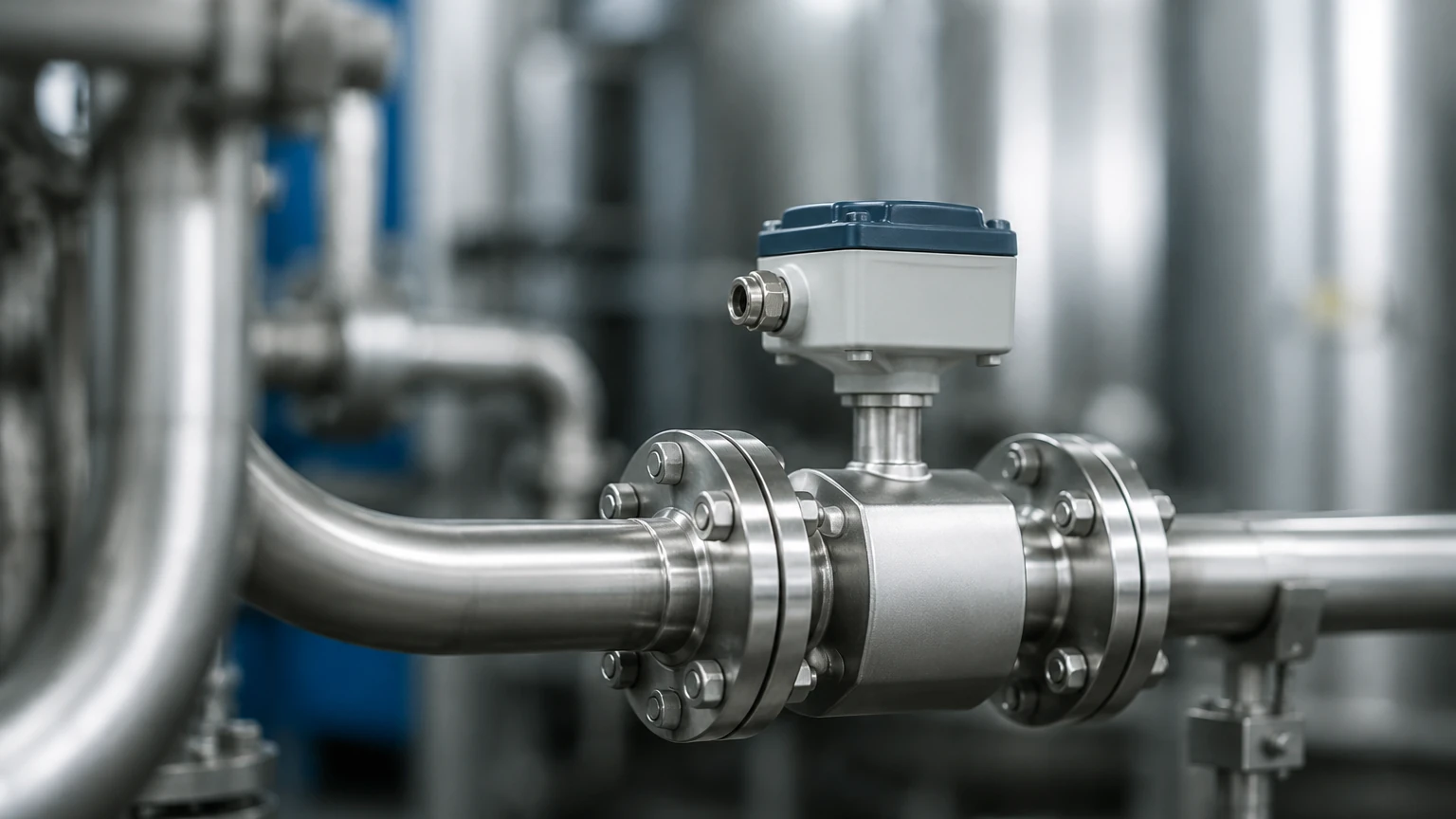
Most flow meters require a specific length of straight pipe both upstream and downstream to ensure a fully developed, non-turbulent flow profile. A common rule of thumb is "10D upstream and 5D downstream," where D is the nominal pipe diameter. However, specific obstructions like elbows, valves, or pumps may necessitate longer runs (up to 40D) or the use of flow conditioners.
Orientation and Mounting
* Liquid Service: Meters should be installed in a position where the pipe is always full. Vertical upward flow is often preferred to prevent air entrapment. Horizontal runs should avoid the top of the pipe where air pockets form.
* Gas Service: Meters should be installed to avoid condensate buildup. In horizontal lines, the sensor should ideally be placed at the top or side of the pipe.
* Grounding: For electromagnetic meters, proper grounding is critical. The fluid, the meter body, and the adjacent piping must be at the same electrical potential to prevent noise from interfering with the low-voltage measurement signal.
Environmental Factors
Temperature and pressure fluctuations can affect fluid density and viscosity, particularly in gas and steam applications. In such cases, multivariable transmitters or separate temperature and pressure compensation may be required to maintain accuracy.
Limitations and Common Risks
Every flow measurement device has physical and operational boundaries. Identifying these risks early prevents costly downtime and measurement errors.
1. Cavitation and Flashing: In liquid applications, if the local pressure drops below the vapor pressure of the liquid, bubbles form (cavitation) or the liquid turns to vapor (flashing). This can damage the meter and cause significant measurement errors.
2. Reynolds Number Limits: Technologies like vortex and DP meters require the fluid to be in a specific flow regime (usually turbulent). At low velocities or high viscosities (low Reynolds numbers), these meters may lose accuracy or stop functioning entirely.
3. Media Compatibility: The wetted parts of the flow measurement device must be chemically compatible with the process fluid. For example, aggressive chemicals in water treatment or oil and gas applications may require exotic liners (like PTFE) or specific metal alloys (like Hastelloy).
4. Signal Interference: For ultrasonic and electromagnetic meters, external electrical noise or vibration can distort the signal. Shielded cabling and strategic placement away from large motors or VFDs are necessary precautions.
Integration with Industrial Automation Systems
Modern flow measurement devices are rarely standalone units. They are integrated into PLC or SCADA systems via various communication protocols. While traditional 4-20mA analog signals remain common, digital protocols like HART, Modbus, and Profibus provide additional diagnostic data, such as internal temperature, tube health, and signal strength.
In applications involving tank inventories, combining flow data with level measurement is standard practice. While level sensors provide the current volume in a vessel, flow meters track the rate of change and total throughput. This redundancy is vital for leak detection and mass balance calculations in chemical and oil and gas facilities.
Frequently Asked Questions (FAQ)
Q: Can I use an electromagnetic flow meter for oil or deionized water?
A: Generally, no. Electromagnetic meters require the fluid to be electrically conductive. Most oils and highly purified deionized water have very low conductivity, which prevents the sensor from generating a measurable voltage.
Q: How do I measure flow in a partially filled pipe?
A: Standard closed-pipe flow meters are designed for full-pipe conditions. For partially filled pipes, you must use specialized area-velocity meters or treat the application as an open channel, using a flume or weir in conjunction with a level measurement device to calculate flow.
Q: What is the difference between turndown ratio and accuracy?
A: Accuracy refers to how close the measurement is to the true value. Turndown ratio (or rangeability) is the ratio of the maximum flow the meter can measure to the minimum flow where it still maintains its rated accuracy. A 10:1 turndown means a meter rated for 100 m³/h can accurately measure down to 10 m³/h.
Q: How often should a flow measurement device be calibrated?
A: Calibration frequency depends on the criticality of the process and the stability of the technology. High-precision Coriolis meters may only need checking every few years, while DP meters with orifice plates may require more frequent inspection for wear or buildup on the plate.
Conclusion
Selecting a flow measurement device is a critical engineering decision that impacts the reliability of the entire process loop. By understanding the underlying measurement principles—from differential pressure to Coriolis mass flow—and adhering to strict installation guidelines, operators can ensure long-term accuracy and minimal maintenance. Whether the application involves simple water treatment or complex chemical processing, the right flow instrumentation provides the data necessary for optimized industrial automation.