Forberg Smith Process Solutions
Forberg Smith Process Solutions
In the landscape of industrial automation, the integration of precise instrumentation is the cornerstone of operational efficiency. Forberg Smith process solutions represent a comprehensive approach to managing complex fluid and material handling systems across industries such as water treatment, chemical processing, and oil and gas. Central to these solutions is the selection and implementation of level measurement technologies. Accurate level data ensures process safety, inventory management, and regulatory compliance.
This guide explores the technical principles of level measurement instruments, their application within integrated process solutions, and the critical factors engineers must consider when selecting hardware for demanding industrial environments.
The Role of Level Measurement in Process Automation
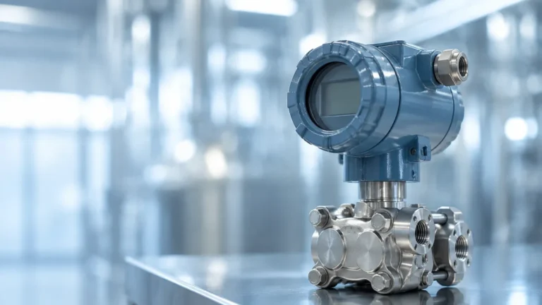
Process solutions are rarely about a single component; they are about how sensors, controllers, and final control elements work in unison. In a typical Forberg Smith process solutions framework, level transmitters provide the primary input for automated control loops. Whether managing the fill rate of a chemical reactor or monitoring the outflow of a wastewater treatment basin, the reliability of the level sensor dictates the stability of the entire system.
Modern industrial level measurement has evolved from simple mechanical floats to sophisticated electronic sensors utilizing electromagnetic waves and ultrasonic pulses. Choosing the right technology requires a deep understanding of the physical properties of the media being measured, the vessel geometry, and the environmental conditions of the site.
Core Technologies in Industrial Level Sensing
Before implementing any process solution, it is essential to understand the measurement principles of the available instruments. Each technology has specific strengths and ideal use cases.
Radar Level Meters (FMCW and Pulse)
Radar level meters are the gold standard for non-contact measurement in high-precision applications. They operate by emitting high-frequency electromagnetic waves (typically in the 26GHz or 80GHz range) toward the material surface. The sensor measures the time it takes for the signal to reflect back.
* FMCW (Frequency Modulated Continuous Wave): These meters transmit a continuous signal with a constantly changing frequency. The difference in frequency between the transmitted and received signal is proportional to the distance. This method offers superior accuracy (up to ±2mm) and is highly effective in environments with vapor or dust.
* Pulse Radar: This technology sends short microwave pulses and measures the time-of-flight. It is often used in simpler applications where extreme precision is less critical than robustness.
Ultrasonic Level Sensors
Ultrasonic sensors utilize sound waves rather than electromagnetic waves. The sensor head emits an ultrasonic pulse that reflects off the surface of the medium. Because the speed of sound is affected by air temperature, these sensors usually include an integrated temperature probe to compensate for fluctuations.
Ultrasonic sensors are highly cost-effective for measuring liquids and slurries in open channels or vented tanks. However, they are sensitive to surface foam, which can absorb the sound pulse, and heavy dust or vacuum conditions, which impede sound wave propagation.
Hydrostatic Level Transmitters
Hydrostatic measurement is a contact-based method that relies on the principle that the pressure at the bottom of a liquid column is proportional to the height of the liquid and its specific gravity. The formula used is $P = \rho \times g \times h$, where $P$ is pressure, $\rho$ is density, $g$ is gravity, and $h$ is height.
These transmitters are typically submersible or flange-mounted at the bottom of a tank. They are exceptionally reliable for deep well monitoring and applications where the liquid surface is turbulent, as the pressure at the bottom remains relatively stable despite surface ripples.
Magnetic Level Gauges
Magnetic gauges provide both local visual indication and the option for remote electronic transmission. They consist of a float containing a high-intensity magnet that moves within a bypass chamber. As the float rises and falls with the liquid level, it flips magnetic flags or rollers on the outside of the chamber. When paired with a reed switch or a magnetostrictive transmitter, they become a powerful part of a process control solution, offering redundant measurement methods.
Selection Criteria for Process Instrumentation
When evaluating Forberg Smith process solutions, engineers must match the instrument's specifications to the application requirements. The following table provides a comparison of common level measurement technologies used in industrial settings.
| Technology | Typical Accuracy | Max Range (m) | Media Compatibility | Temperature/Pressure Limits |
| :— | :— | :— | :— | :— |
| 80GHz Radar | ±2 mm | 120m | Liquids, Solids, Corrosives | High (Up to 250°C / 40 bar) |
| Ultrasonic | ±0.25% of range | 15m – 20m | Liquids, Slurries | Moderate (Up to 80°C / 3 bar) |
| Hydrostatic | ±0.1% to ±0.5% | 200m+ | Clean Liquids, Wastewater | Moderate (Up to 100°C) |
| Magnetic Gauge | Visual / ±5 mm | 6m+ | Clean or Dirty Liquids | High (Up to 400°C / 160 bar) |
Key Evaluation Factors
1. Dielectric Constant (dk): For radar measurement, the reflectivity of the material depends on its dielectric constant. Materials with a low dk (like oils) reflect less energy than those with a high dk (like water), necessitating more sensitive radar units.
2. Vessel Internal Geometry: Agitators, ladders, and heating coils can create false echoes. Advanced radar and ultrasonic units offer "false echo suppression" software to ignore these obstructions.
3. Chemical Compatibility: The wetted parts of the sensor (diaphragms, antennas, or floats) must be compatible with the process media. Common materials include 316L Stainless Steel, PTFE, and Hastelloy.
Installation and Commissioning Guidelines
Proper installation is critical to the performance of any level measurement system. Even the most advanced sensor will fail to provide accurate data if poorly positioned.
* Mounting Location: Sensors should be mounted away from the tank wall to avoid interference from side-wall reflections. For radar and ultrasonic units, the beam should have a clear path to the liquid surface, avoiding the fill stream.
* Dead Zone (Blocking Distance): Every non-contact sensor has a "dead zone" near the sensor face where measurement is impossible. Ensure the maximum expected liquid level does not enter this zone.
* Orientation: Hydrostatic sensors must be protected from high-velocity flow streams (which can cause venturi effects and false pressure readings). Stilling wells are often used in turbulent tanks to provide a calm environment for the sensor.
* Calibration: While many modern sensors are "plug-and-play," field calibration is necessary to account for specific gravity (in hydrostatic sensors) or to map the tank profile (in radar sensors). For more detailed product specifications and technical support, engineers can refer to the Main Page of the manufacturer's resource center.

Limitations and Environmental Challenges
No single technology is a universal solution. Understanding the limitations of Forberg Smith process solutions helps in mitigating risks during the design phase.
* Foam and Turbulence: Thick foam can dissipate ultrasonic pulses and weaken radar signals. In such cases, a stilling well or a guided wave radar (GWR) may be required to ensure a stable signal.
* Vacuum Conditions: Ultrasonic waves cannot travel through a vacuum. For vacuum distillation or similar processes, radar or hydrostatic transmitters are the only viable options.
* Temperature Extremes: High temperatures can cause electronic drift or damage sensor diaphragms. Remote-mounted electronics or specialized cooling fins are often necessary for applications exceeding 150°C (302°F).
* Vapor and Condensation: Condensation on an ultrasonic transducer face can "blind" the sensor. Radar units with PTFE drip-off antennas are designed to shed moisture and maintain signal integrity in high-humidity environments.
Frequently Asked Questions (FAQ)
Q: How does the dielectric constant affect radar level measurement?
A: The dielectric constant (dk) measures a material's ability to reflect electromagnetic energy. Water has a high dk (~80) and is easy to measure. Hydrocarbons often have low dk values (1.7 to 2.5), which means they reflect very little energy. For low dk materials, high-frequency radar or guided wave radar is recommended to ensure a reliable return signal.
Q: When should I use a hydrostatic transmitter instead of an ultrasonic sensor?
A: Hydrostatic transmitters are preferred when there is heavy foam on the liquid surface, when the tank is under high pressure (and not vented), or when the measurement range is very deep (e.g., a 100m borehole). Ultrasonic sensors are better for corrosive liquids where non-contact measurement is desired to prevent sensor degradation.
Q: Can radar level meters measure solids like grain or cement?
A: Yes, but it requires specific considerations. Solids do not have a flat surface; they form cones or depressions. High-frequency 80GHz radar is typically used for solids because its narrow beam angle can better target the material surface and minimize interference from the steep angles of the material piles.
Q: What maintenance is required for magnetic level gauges?
A: Magnetic gauges are relatively low-maintenance. However, in applications with magnetic particles or heavy scaling, the chamber should be flushed periodically to prevent the float from sticking. Most units include a drain plug at the bottom of the chamber for this purpose.
Conclusion
Implementing effective Forberg Smith process solutions requires a balance of theoretical knowledge and practical application engineering. By understanding the underlying physics of radar, ultrasonic, and hydrostatic measurement, and by adhering to strict installation standards, industrial operators can achieve high levels of accuracy and reliability. As processes become increasingly automated, the quality of the primary level data remains the most critical factor in system performance. For those seeking to optimize their instrumentation suites, reviewing the full range of available technologies on the Main Page is a recommended first step in the procurement process.