Intrinsically Safe Sensors
Intrinsically Safe Sensors
In industrial environments where flammable gases, vapors, or combustible dusts are present, the risk of ignition is a primary engineering concern. Level measurement in these hazardous areas requires specialized instrumentation designed to prevent electrical or thermal energy from triggering an explosion. Intrinsically safe sensors represent a critical protection methodology, focusing on limiting the energy available within a circuit so that even under fault conditions, an incendiary spark or hot surface cannot occur.
For process engineers and system integrators, selecting the correct level measurement technology involves balancing accuracy requirements with rigorous safety standards such as ATEX, IECEx, or North American Class/Division systems. This guide explores the principles of intrinsic safety (IS) as applied to level sensors, detailing how various technologies—including radar, ultrasonic, and hydrostatic transmitters—are adapted for these high-risk applications.
Principles of Intrinsic Safety in Level Measurement
Intrinsic safety is a protection technique based on the limitation of electrical energy within equipment and interconnecting wiring exposed to a potentially explosive atmosphere. Unlike explosion-proof (Ex d) enclosures, which are designed to contain an internal explosion, intrinsically safe (Ex i) systems are designed to prevent the explosion from happening in the first place.
The Entity Concept
The implementation of intrinsically safe sensors relies on the "Entity Concept." This framework allows for the interconnection of devices from different manufacturers provided their safety parameters are compatible. When evaluating a level measurement loop, engineers must verify the following parameters:
* Vmax (Ui): The maximum voltage the sensor can receive.
* Imax (Ii): The maximum current the sensor can receive.
* Pmax (Pi): The maximum power the sensor can receive.
* Ci: Internal capacitance of the sensor.
* Li: Internal inductance of the sensor.
* Ccable / Lcable: The capacitance and inductance of the interconnecting wiring.
For a system to be safe, the associated apparatus (usually a Zener barrier or galvanic isolator located in the safe area) must provide output parameters (Uo, Io, Po) that do not exceed the sensor's input ratings, and the total capacitance and inductance of the loop must remain below the limits specified for the gas group present.
Energy Limitation Principles
Level sensors achieve intrinsic safety through specific circuit designs:
1. Current Limitation: Using series resistors to prevent excessive current flow.
2. Voltage Limitation: Using shunt Zener diodes to clamp the voltage to a safe level.
3. Energy Storage Reduction: Minimizing the use of large capacitors and inductors that could release stored energy in a spark.
Level Measurement Technologies for Hazardous Areas
Before selecting a specific instrument, it is essential to understand how different measurement principles interact with IS requirements. You can Review product options and application support to see how these technologies are implemented in certified hardware.
1. Radar Level Meters (Non-Contact)
Radar sensors, particularly Frequency Modulated Continuous Wave (FMCW) or Pulse Radar, are widely used in hazardous areas. Because they do not come into direct contact with the medium, they are ideal for volatile chemicals and hydrocarbons. IS radar sensors use extremely low-power microwave pulses. The challenge for manufacturers is maintaining a high signal-to-noise ratio while operating within the strict power limits (Pi) imposed by IS certifications.
2. Ultrasonic Level Sensors
Ultrasonic sensors measure the time-of-flight of sound waves. In hazardous environments, the piezoelectric crystal must be driven by a limited voltage. While effective for water treatment and some chemical applications, ultrasonic sensors are limited in IS environments by the power required to penetrate heavy vapors or foam, which are common in explosive zones.
3. Hydrostatic Level Transmitters
These sensors measure the pressure exerted by a liquid column. In an IS configuration, the pressure diaphragm and the 4-20mA electronics are encapsulated. Since these sensors are often submerged (Zone 0), they require the highest level of IS protection (Ex ia). The vented cable used for atmospheric pressure compensation must also be integrated into the safety plan to prevent it from becoming a conduit for hazardous gases.
4. Magnetic Level Gauges and Switches
Magnetic level gauges are often considered "simple apparatus" if they contain only passive switches. However, when equipped with a continuous transmitter, they must follow IS protocols. The interaction between the internal float and the external sensor rail allows for clear local indication while providing a safe electronic signal to the control room.
Practical Selection Table
The following table provides a comparison of common level measurement technologies in the context of intrinsically safe applications.
| Technology | Typical IS Rating | Suitable Zones | Ideal Applications | Primary Limitation |
| :— | :— | :— | :— | :— |
| Radar | Ex ia IIC T6 | Zone 0, 1, 2 | Volatile fuels, acids, solvents | Higher initial cost |
| Ultrasonic | Ex ib IIB T4 | Zone 1, 2 | Wastewater, open sumps | Affected by vapor/foam |
| Hydrostatic | Ex ia IIC T4 | Zone 0, 1, 2 | Deep wells, fuel tanks | Contact with medium |
| Float Switch | Simple Apparatus | Zone 0, 1, 2 | High/Low level alarms | Moving parts can foul |
| Capacitance | Ex ia IIC T6 | Zone 0, 1, 2 | Interface measurement | Requires dielectric stability |
Installation Considerations and Best Practices
Correct installation is as critical as the sensor certification itself. Failure to follow IS installation standards (such as IEC 60079-14) can invalidate the protection method.
Wiring and Separation
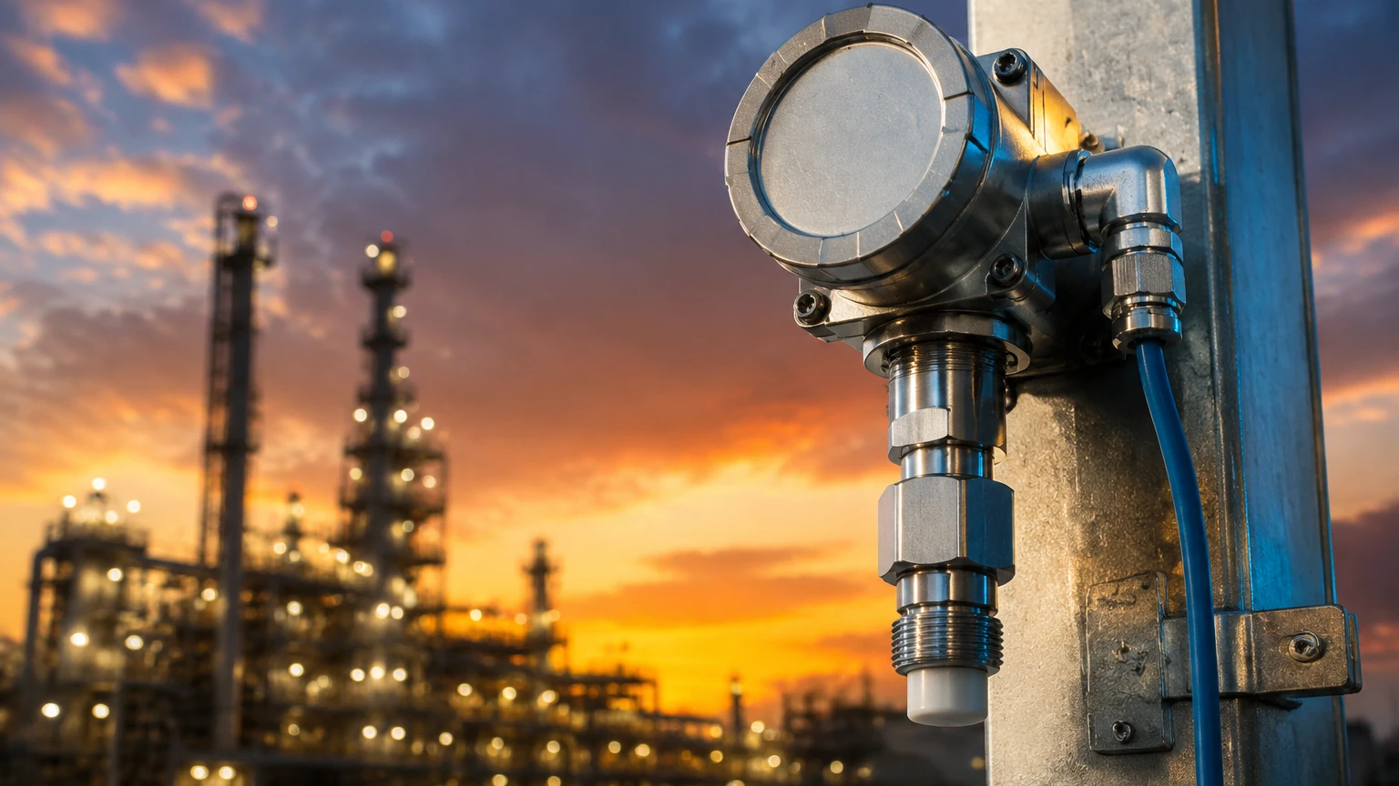
Intrinsically safe circuits must be physically separated from non-IS circuits. This is typically achieved by a minimum 50mm air gap or a physical barrier. Cables for intrinsically safe sensors are traditionally colored light blue to distinguish them from standard power and signal lines. This prevents maintenance personnel from accidentally connecting a high-power source to a protected loop.
Grounding and Bonding
In systems using Zener barriers, a high-integrity "IS Ground" is required. This ground must have a resistance of less than 1 Ohm to ensure that fault currents are safely diverted away from the hazardous area. Galvanic isolators, which provide electrical isolation between the input and output circuits, generally do not require this specialized ground, making them a preferred choice in many modern installations.
Cable Parameters
For long cable runs (e.g., over 200 meters), the capacitance (Cc) and inductance (Lc) of the cable can become significant. If the total capacitance (Ci + Cc) exceeds the allowable limit (Co) of the barrier, the system is no longer intrinsically safe. Engineers must calculate these values based on the cable manufacturer's data sheets before commissioning.
Limitations of Intrinsically Safe Systems
While IS is the most flexible protection method, it has inherent limitations:
* Power Constraints: High-power devices, such as heated sensors or large motor-driven level gauges, cannot be made intrinsically safe. They must use explosion-proof or purged enclosures.
* Distance Limits: The voltage drop across IS barriers and the cumulative capacitance of long cables can limit the effective range of a 4-20mA signal.
* Complexity of Documentation: Every component in the loop must be documented in a descriptive system document (DSD) to prove the loop's safety to inspectors.
Frequently Asked Questions (FAQs)
Q: Can I use a standard multimeter to test an intrinsically safe sensor in a hazardous area?
A: No. Only test equipment specifically certified as intrinsically safe may be used within the hazardous zone. Standard multimeters can introduce enough energy to cause an ignition.
Q: What is the difference between "Ex ia" and "Ex ib"?
A: "Ex ia" equipment is designed to remain safe with two independent faults and is suitable for Zone 0 (constantly hazardous). "Ex ib" is safe with one fault and is suitable for Zone 1 (occasionally hazardous).
Q: Does a simple float switch need certification?
A: Under many standards, a simple switch is considered a "Simple Apparatus" (like a resistor or thermocouple). It does not require a specific IS certificate but must still be connected to an IS barrier and be clearly labeled within the system documentation.
Q: How do temperature classes (T-ratings) affect sensor selection?
A: The T-rating (e.g., T4, T6) indicates the maximum surface temperature the sensor can reach under fault conditions. You must ensure the sensor's T-rating is lower than the auto-ignition temperature of the gases present in your facility.
Conclusion
Implementing intrinsically safe sensors for level measurement is a fundamental requirement for safety in the oil and gas, chemical, and pharmaceutical industries. By understanding the principles of energy limitation, verifying entity parameters, and adhering to strict installation guidelines, engineers can ensure reliable data collection without compromising site safety. For detailed technical specifications and to explore specific instrument configurations for your application, visit the Main Page of our technical reference center.