API 2350
API 2350
In the petroleum and chemical industries, the prevention of tank overfills is a critical safety and environmental priority. The industry standard governing these practices is API 2350, titled "Overfill Protection for Storage Tanks in Petroleum Facilities." Developed by the American Petroleum Institute, this standard provides the essential requirements for management systems and hardware used to prevent hazardous spills from aboveground atmospheric storage tanks. For engineers and facility managers, compliance with api 2350 is not merely a regulatory hurdle but a fundamental component of risk management and operational integrity.
Understanding the Scope of API 2350
API 2350 applies specifically to atmospheric storage tanks that store Class I and Class II liquids (flammable and combustible liquids). The standard outlines how facilities should manage tank levels to prevent an overfill event, which occurs when a liquid exceeds the "Maximum Working Level" and reaches a point where it may escape the primary containment.
The standard emphasizes a "defense-in-depth" strategy. This involves a combination of administrative controls (procedures and training) and engineering controls (level sensors, alarms, and automated shutdown systems). By integrating these elements, facilities can significantly reduce the probability of human error or mechanical failure leading to an environmental disaster.
Measurement Principles for Overfill Protection
To meet the requirements of api 2350, reliable level measurement is indispensable. Before selecting specific hardware, it is vital to understand the physical principles that govern how these instruments detect liquid levels. In the context of petroleum storage, three primary technologies are commonly employed: Radar, Ultrasonic, and Point-Level Switches.
Radar Level Measurement
Radar technology is the gold standard for high-accuracy applications in the oil and gas sector. It operates on the Time-of-Flight (ToF) principle. A sensor emits a microwave signal toward the liquid surface. The signal reflects off the surface and returns to the sensor. By measuring the time it takes for the signal to travel, the instrument calculates the distance and, consequently, the liquid level.
* Non-contact Radar: These units are mounted at the top of the tank and do not touch the medium. They are ideal for volatile liquids as they are unaffected by vapor space conditions or changes in density.
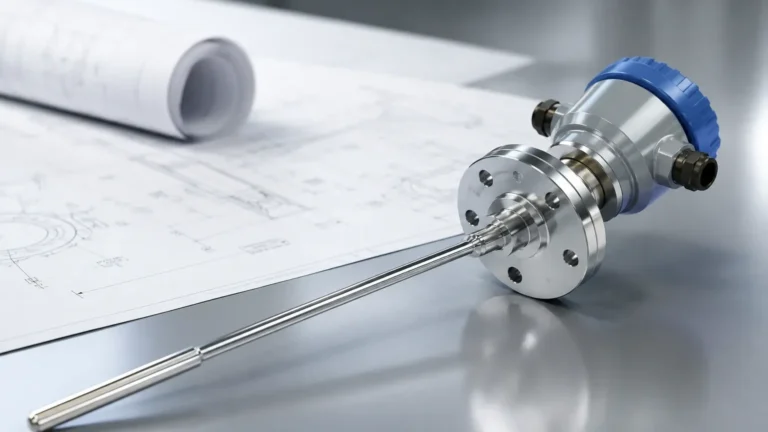
* Guided Wave Radar (GWR): These use a probe (rod or cable) to guide the microwave signal. GWR is particularly effective in tanks with internal obstructions or where foam might interfere with a non-contact signal.
Ultrasonic Level Measurement
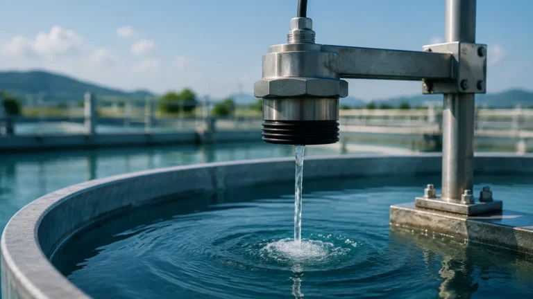
Ultrasonic sensors also use the ToF principle but utilize sound waves instead of microwaves. A transducer emits an ultrasonic pulse that bounces off the liquid surface. While cost-effective, ultrasonic sensors can be sensitive to temperature fluctuations, heavy vapors, and surface turbulence, making them more suitable for water treatment or stable chemical storage rather than high-volatility petroleum products.
Point-Level Detection
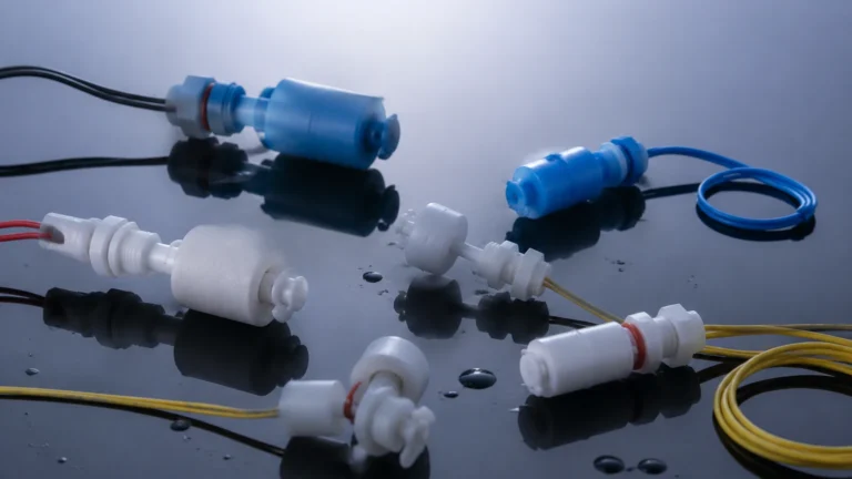
Unlike continuous measurement, point-level switches (such as tuning forks or float switches) are designed to trigger an alarm at a specific, predetermined height. In an api 2350 compliant system, these often serve as the High-High (LAHH) alarm, providing a redundant and independent layer of protection from the primary continuous level gauge.
Tank Categories and System Requirements
API 2350 classifies tanks into three distinct categories based on how they are monitored and the level of automation involved in their overfill protection systems. Understanding these categories is essential for choosing the right instrumentation from our Main Page.
Category 1: Fully Manual Systems
In Category 1 tanks, the overfill protection relies entirely on manual operations. Personnel must be physically present to monitor the level and manually stop the flow. This category is increasingly rare in modern facilities due to the high risk of human error. The standard requires strict adherence to attendance and manual gauging procedures.
Category 2: Manual Systems with Alarms
These tanks are equipped with an Automatic Tank Gauge (ATG) that provides a continuous level reading to a remote location (such as a control room). Category 2 systems must also include an independent high-level alarm. While the system alerts the operator to a potential overfill, the final action to stop the flow remains a manual process.
Category 3: Automated Overfill Protection Systems (AOPS)
Category 3 represents the highest level of safety. These systems include an ATG and an independent AOPS. If the liquid reaches a critical level, the AOPS automatically triggers a safety function, such as closing an inlet valve or stopping a pump, without requiring operator intervention. This setup is mandatory for tanks where the risk and consequences of an overfill are high.
Selecting Level Instrumentation for API 2350 Compliance
When selecting instruments to comply with api 2350, engineers must evaluate the reliability, accuracy, and compatibility of the device with the stored medium. The following table provides a comparison of common technologies used in overfill prevention.
| Technology | Accuracy | Suitability for API 2350 | Maintenance Requirements | Limitations |
| :— | :— | :— | :— | :— |
| Non-contact Radar | High (±1-3 mm) | Excellent for Cat 2 & 3 | Low (no moving parts) | Higher initial cost |
| Guided Wave Radar | High (±2 mm) | Excellent for narrow tanks | Low to Moderate | Probe can accumulate buildup |
| Ultrasonic | Moderate (±5-10 mm) | Suitable for non-volatile | Moderate | Sensitive to vapor and foam |
| Tuning Fork Switch | High (Point) | Ideal for LAHH Alarms | Low | Point detection only |
| Float Switch | Moderate (Point) | Acceptable for Cat 1 & 2 | High (moving parts) | Risk of mechanical jamming |
Installation and Maintenance Guidelines
Proper installation is as critical as device selection for api 2350 compliance. Even the most advanced radar level meter will fail to provide accurate data if installed incorrectly.
Installation Considerations
1. Nozzle Positioning: For radar and ultrasonic sensors, the nozzle should be located away from the tank wall to avoid false reflections. For a tank with a diameter of 10 meters, the sensor should typically be placed at least 1 meter from the wall.
2. Stilling Wells: In tanks with high turbulence or internal structures (like heating coils), installing the sensor inside a stilling well can provide a stable surface for measurement. The stilling well must be vertically aligned and perforated to ensure the level inside matches the tank level.
3. Independent Mounting: API 2350 emphasizes independence. The secondary high-high alarm sensor should ideally be mounted on a separate nozzle and use a different power source and signal path than the primary level gauge to avoid common-mode failures.
Maintenance and Proof Testing
The standard requires regular "proof testing" of the overfill protection system. This involves verifying that the sensors, alarms, and logic solvers (in AOPS) function correctly.
* Visual Inspection: Check for corrosion, wiring integrity, and physical damage.
* Functional Test: Simulate a high-level condition to ensure the alarm triggers at the correct setpoint.
* Calibration: Periodically verify the accuracy of continuous level gauges against a manual tape measure (hand dip).
Safety Parameters and Response Times
A core requirement of api 2350 is the calculation of response times. The "Overfill Alarm" must be set at a level that allows sufficient time for the operator or the automated system to stop the flow before the liquid reaches the "Critical High Level."
For manual systems (Category 2), the standard often suggests a minimum response time of 30 minutes, although this varies based on flow rates and facility procedures. For automated systems (Category 3), the response time is determined by the closing time of valves and the deceleration of the fluid column, often requiring only a few minutes of buffer.
Frequently Asked Questions (FAQs)
Q: Does API 2350 require redundant sensors for all tanks?
A: No. The requirement for redundancy depends on the tank category. Category 3 tanks require an independent AOPS, which effectively means a second, independent sensor for the high-high alarm. Category 1 tanks do not require electronic redundancy but rely on manual oversight.
Q: Can I use the same sensor for inventory management and overfill protection?
A: While a single high-accuracy radar can perform both tasks, api 2350 strongly recommends (and in Category 3, requires) an independent alarm system. Using a separate device for the overfill alarm ensures that if the primary inventory gauge fails, the safety system remains operational.
Q: How often should I perform proof testing?
A: The frequency of proof testing is typically determined by the facility's risk assessment and the manufacturer's recommendations. However, common industry practice for api 2350 compliance involves annual functional testing of the alarm systems.
Q: Is radar better than ultrasonic for petroleum tanks?
A: Generally, yes. Petroleum products often produce vapors that change the speed of sound, which can cause errors in ultrasonic measurements. Radar uses electromagnetic waves, which are not affected by the gas composition in the tank's headspace, providing much higher reliability.
Conclusion
Adhering to api 2350 is a multi-faceted endeavor that combines rigorous management practices with high-performance instrumentation. By understanding the measurement principles of radar and ultrasonic sensors and correctly categorizing storage assets, facilities can implement robust overfill protection strategies. For those looking to upgrade their existing systems or design new installations, we invite you to Review product options and application support to find the most reliable solutions for your specific industrial needs. Ensuring safety today prevents the environmental and financial costs of an overfill tomorrow.