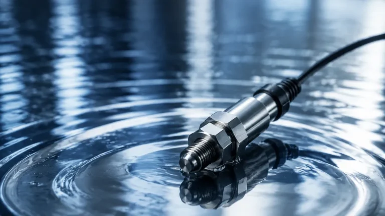
Differential Pressure Sensor Applications
Differential Pressure Sensor Applications
Differential pressure (DP) sensors are fundamental components in industrial process control, serving as the primary mechanism for measuring not only pressure differences but also level, flow, and density. By calculating the difference between two pressure points in a system, these instruments provide critical data for automation and safety. In the context of industrial level measurement, DP sensors are particularly valued for their ability to provide accurate readings in pressurized vessels where standard hydrostatic or ultrasonic methods may face challenges.
Understanding the diverse range of differential pressure sensor applications requires a technical grasp of the underlying physics and the specific environmental factors that influence instrument selection. This guide examines the principles of DP measurement, its primary industrial uses, and the engineering considerations necessary for successful deployment.
Understanding Differential Pressure Measurement Principles
The fundamental principle of a differential pressure sensor is the measurement of the difference between two applied pressures, typically referred to as the High-Pressure side ($P_{high}$) and the Low-Pressure side ($P_{low}$). The resulting value, $\Delta P$, is expressed as:
$$\Delta P = P_{high} – P_{low}$$
In most industrial transmitters, this pressure difference is applied to a sensing element, such as a flexible diaphragm. The displacement of the diaphragm is converted into an electrical signal (typically 4-20mA or a digital protocol like HART or Modbus) through various technologies, including piezoresistive, capacitive, or silicon-resonant sensing.
Hydrostatic Level Principle
In level measurement, the sensor utilizes the hydrostatic pressure of a liquid column. For an open (vented) tank, the $P_{low}$ side is vented to the atmosphere, while the $P_{high}$ side is connected to the bottom of the tank. The pressure exerted is proportional to the height of the liquid ($h$) and its density ($\rho$):
$$P = \rho \cdot g \cdot h$$
Where $g$ is the gravitational constant ($9.81 m/s^2$). When the tank is pressurized, the $P_{low}$ side must be connected to the vapor space at the top of the vessel to cancel out the static pressure, ensuring the sensor only measures the pressure exerted by the liquid column itself.
Key Industrial Applications of DP Sensors
Differential pressure sensor applications span across various sectors, from water treatment to chemical processing and oil and gas. Their versatility stems from their ability to infer multiple process variables from a single pressure differential.
1. Liquid Level Measurement in Pressurized Tanks
This is perhaps the most common application in process industries. Unlike open tanks where a simple hydrostatic transmitter suffices, closed vessels (such as boilers, fermenters, or liquefied gas tanks) contain a pressurized vapor space. A DP sensor compensates for this overhead pressure by measuring the difference between the bottom of the tank and the top. This ensures that changes in the internal tank pressure do not result in false level readings.
2. Flow Rate Measurement
By using a primary flow element—such as an orifice plate, Venturi tube, or flow nozzle—a DP sensor can measure the flow rate of liquids, gases, or steam. As the fluid passes through a constriction in the pipe, its velocity increases and its pressure decreases (Bernoulli’s principle). The square root of the pressure drop across the constriction is proportional to the flow rate. This method is highly reliable and remains a global standard for high-pressure steam and large-diameter water pipes.
3. Filter and Heat Exchanger Monitoring
In industrial filtration systems, DP sensors are used to monitor the "health" of the filter media. As contaminants build up on the filter, the resistance to flow increases, causing the pressure drop across the filter to rise. By setting a specific $\Delta P$ threshold, operators can automate backwashing cycles or receive alerts for manual filter replacement. Similarly, in heat exchangers, a rising differential pressure can indicate scaling or fouling within the tubes.
4. Interface Level Measurement
In separators where two immiscible liquids of different densities coexist (such as oil and water), DP sensors can be calibrated to detect the interface level. By knowing the specific gravities of both fluids, the sensor can distinguish between the total level and the point where the two liquids meet, which is crucial for discharge control in chemical and petrochemical processes.
Selection Criteria for Differential Pressure Transmitters
Selecting the correct instrument requires a balance between accuracy, environmental resilience, and cost. The following table provides a reference for the primary factors engineers must evaluate.
| Selection Factor | Description | Engineering Consideration |
| :— | :— | :— |
| Pressure Range | The maximum $\Delta P$ expected in the process. | Ensure the sensor can handle overpressure events without damage. |
| Static Pressure | The total pressure within the system (not the difference). | The transmitter body must be rated for the maximum system pressure (e.g., 100 bar). |
| Wetted Materials | Materials in contact with the process fluid. | Use SS316L for water; Hastelloy or Tantalum for corrosive chemicals. |
| Accuracy Class | The allowable margin of error (e.g., 0.075% FS). | Higher accuracy is required for custody transfer flow measurement. |
| Output Protocol | How the data is transmitted to the PLC/DCS. | 4-20mA is standard; HART/RS485 allows for remote diagnostics. |
| Process Temperature | The temperature of the fluid at the sensing point. | High temperatures may require remote seals or cooling siphons. |
| Turndown Ratio | The ratio of the maximum to minimum measurable span. | A high turndown ratio (e.g., 100:1) allows one sensor to cover multiple ranges. |
For a comprehensive overview of available technologies and specific product models, engineers should consult the Main Page to review detailed technical specifications and application support.
Installation Best Practices and Engineering Considerations
The accuracy of a differential pressure sensor is heavily dependent on its installation. Improper mounting can lead to "zero drift" or sluggish response times.
Impulse Line Configuration
Impulse lines are the small-diameter pipes that connect the process vessel to the transmitter.
* Gas Applications: The transmitter should ideally be mounted above the process tapping points to allow any condensed liquid to drain back into the process.
* Liquid Applications: The transmitter should be mounted below the tapping points so that any trapped gas bubbles can rise back into the vessel, preventing air pockets from affecting the pressure reading.
Wet Leg vs. Dry Leg
In pressurized level applications, the $P_{low}$ (reference) line can be configured in two ways:
* Dry Leg: Used when the vapor in the tank will not condense at ambient temperatures. The reference line remains filled with gas.
* Wet Leg: Used when the vapor is likely to condense (e.g., steam). The reference line is intentionally filled with a known liquid (usually the process fluid or water) to provide a constant head pressure that is then mathematically offset in the transmitter calibration.
Remote Seals and Capillaries
For highly corrosive, viscous, or high-temperature fluids, remote seals (diaphragm seals) are used. These seals isolate the transmitter from the process fluid using a flexible diaphragm and a capillary tube filled with silicone oil or another transmission fluid. While this protects the sensor, engineers must account for the temperature-induced expansion of the fill fluid, which can introduce small measurement errors if capillaries are long or exposed to direct sunlight.

Potential Limitations and Mitigation Strategies
While DP sensors are versatile, they are not without limitations. Engineers must be aware of the following challenges:
1. Density Sensitivity: Since DP level measurement relies on the formula $P = \rho gh$, any change in the liquid's density (caused by temperature fluctuations or concentration changes) will result in a level error. Modern smart transmitters can compensate for this if a secondary temperature or density input is provided.
2. Clogging: In slurries or fluids with high solids content, impulse lines can become blocked. Utilizing flush-mounted diaphragm seals or regular purging cycles can mitigate this risk.
3. Mechanical Complexity: Compared to non-contact methods like radar, DP sensors require physical process connections (tappings). This increases the number of potential leak points, requiring regular inspection of gaskets and manifolds.
Frequently Asked Questions (FAQs)
Q: How often should a differential pressure sensor be calibrated?
A: In most industrial applications, a yearly calibration check is standard. However, in critical safety loops or high-accuracy flow applications, semi-annual calibration may be required. Many modern digital sensors offer "self-diagnostics" that can extend the necessary interval between manual calibrations.
Q: Can a DP sensor measure the level of a boiling liquid?
A: Yes, but it requires a "wet leg" or a remote seal system. Boiling liquids create vapor that will condense in the reference line; a wet leg ensures the reference pressure remains stable despite the boiling action.
Q: What is the difference between a pressure transmitter and a differential pressure transmitter?
A: A standard pressure transmitter has one process connection and measures pressure relative to atmospheric pressure (gauge) or a vacuum (absolute). A differential pressure transmitter has two connections and measures the difference between them.
Q: How do I handle measurement in tanks with varying internal pressure?
A: This is the primary use case for DP sensors. By connecting the low-pressure side to the top of the tank, the internal vessel pressure is applied to both sides of the sensor diaphragm, effectively canceling it out and leaving only the hydrostatic pressure of the liquid.
Conclusion
Differential pressure sensor applications are a cornerstone of modern industrial instrumentation. Their ability to adapt to pressurized environments, monitor filter integrity, and provide precise flow data makes them indispensable in complex process loops. By carefully considering the fluid properties, vessel dynamics, and installation requirements, engineers can ensure long-term reliability and accuracy. For those seeking specific hardware solutions or customized OEM/ODM services for level and pressure measurement, visiting the Main Page offers access to a wide range of industrial-grade instruments designed for the most demanding applications.