Thermocouple Well
Thermocouple Well
In industrial process control, the accuracy of temperature data is often as critical as the protection of the sensors providing it. A thermocouple well, commonly referred to as a thermowell, is a cylindrical fitting designed to protect temperature sensors—such as thermocouples, RTDs, and bimetal thermometers—from the harsh conditions of a process media. By acting as a barrier between the sensor and the fluid, the thermocouple well allows for the removal and replacement of instruments without requiring a system shutdown or the drainage of pipes and vessels.
While temperature measurement is a distinct field, it is deeply intertwined with other process variables. For instance, accurate temperature data is essential for density compensation in hydrostatic level measurement and for calculating the speed of sound in ultrasonic level applications. Understanding the engineering principles behind thermocouple well design ensures both the longevity of the instrumentation and the safety of the industrial facility.
Measurement Principles and Heat Transfer
A thermocouple well functions as a heat exchanger. For a sensor located inside the well to provide an accurate reading, heat must transfer from the process medium, through the wall of the well, and into the sensing element. This process is governed by the laws of conduction, convection, and radiation.
Thermal Lag and Response Time
The presence of a thermocouple well introduces "thermal lag." Because the well has mass and specific heat capacity, it takes time for the temperature of the well to equalize with the temperature of the process fluid. The thickness of the well wall and the material’s thermal conductivity directly impact the response time. In high-speed processes where temperature fluctuations occur rapidly, thin-walled or stepped-shank wells are often preferred to minimize this delay.
Conduction Error
Conduction error occurs when heat is transferred along the length of the thermocouple well to the ambient environment outside the vessel. If the well is not sufficiently immersed in the fluid, the sensor may report a temperature that is influenced by the external pipe wall or atmospheric conditions. To mitigate this, engineers typically follow the "10-times diameter" rule, ensuring the immersion length is at least ten times the outer diameter of the well tip.
Types of Thermocouple Well Designs
Thermocouple wells are categorized by their connection to the process and their physical shape. The choice depends on the pressure, temperature, velocity, and corrosivity of the medium.
1. Connection Types
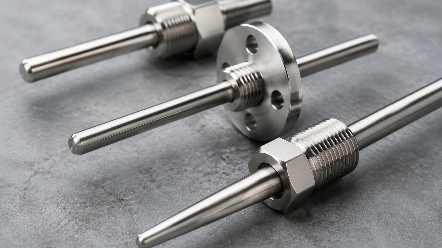
* Threaded Wells: These are screwed into a process pipe or vessel. They are cost-effective and common in low-pressure applications. Standard sizes include 1/2", 3/4", and 1" NPT.
* Flanged Wells: These feature a flange that bolts to a mating flange on the process equipment. They are used in high-pressure, high-temperature, or highly corrosive environments where a robust seal is mandatory.
* Socket Weld Wells: These are welded into a socket coupling. They provide a permanent, leak-proof connection suitable for high-pressure steam or hazardous chemicals.
* Weld-in Wells: These are welded directly into the process wall. They are used when a permanent installation is required and pressure ratings are extreme.
2. Shank Profiles
* Straight Shank: The diameter is uniform from the base to the tip. These are simple to manufacture and offer good structural integrity.
* Tapered Shank: The diameter decreases linearly toward the tip. This design provides a high strength-to-weight ratio and a faster response time due to the reduced mass at the sensing point.
* Stepped Shank: The diameter is reduced abruptly at the tip (e.g., from 19 mm to 12.7 mm). This offers the fastest response time while maintaining a rigid base to withstand high flow velocities.
Material Selection and Chemical Compatibility
The material of the thermocouple well must be compatible with the process fluid to prevent premature failure due to corrosion or erosion. While Stainless Steel 316 (SS316) is the industry standard for many water treatment and mild chemical applications, more aggressive environments require specialized alloys.
| Material | Common Applications | Temperature Limit (Approx.) |
| :— | :— | :— |
| 316/316L Stainless Steel | Water, food processing, general chemicals | 850°C |
| Hastelloy C-276 | Strong acids, chlorine, sour gas | 1000°C |
| Inconel 600 | High-temperature oxidation, heat treating | 1150°C |
| Monel 400 | Sea water, hydrofluoric acid | 500°C |
| PTFE Coated | Highly corrosive low-temperature acids | 200°C |
In applications involving abrasive slurries, thermocouple wells may be hard-faced with materials like Stellite to resist erosion. For high-velocity steam, the mechanical strength of the material is often more critical than its chemical resistance.
Engineering Evaluation: The Wake Frequency Calculation
One of the most common causes of thermocouple well failure is not corrosion, but mechanical fatigue caused by fluid flow. As fluid flows past a cylindrical well, it creates a phenomenon known as "vortex shedding." This creates alternating low-pressure zones that cause the well to vibrate.
If the frequency of these vibrations (the wake frequency) matches the natural frequency of the thermocouple well, resonance occurs. This can lead to catastrophic failure, where the well snaps off and enters the process stream, potentially damaging downstream equipment like pumps or turbines.
Engineers use the ASME PTC 19.3 TW standard to calculate the safety of a thermowell design. This evaluation considers:
1. Static Stress: The pressure exerted by the fluid.
2. Dynamic Stress: The forces caused by vortex shedding.
3. Hydrostatic Pressure: The external pressure limit of the well material.
4. Frequency Ratio: Ensuring the wake frequency does not exceed 80% of the well's natural frequency.
Integration with Level Measurement Systems
In many industrial setups, temperature measurement via a thermocouple well is a prerequisite for accurate level sensing. For example, when using hydrostatic level transmitters, the sensor measures the pressure exerted by a liquid column. However, as the temperature of the liquid changes, its density also changes. Without an accurate temperature reading from a nearby thermocouple well, the level calculation could be off by several percentage points.
Similarly, ultrasonic level sensors depend on the speed of sound, which varies significantly with air temperature. Precise temperature compensation ensures that the time-of-flight measurement is correctly translated into distance. For engineers seeking comprehensive instrumentation for these challenges, it is helpful to Review product options and application support to ensure that temperature and level sensors are correctly paired for the specific process conditions.
Installation Considerations
Proper installation is vital for both the accuracy of the measurement and the structural integrity of the system. The following guidelines should be observed:
1. Immersion Depth
To avoid conduction errors, the sensing tip should be located in the center third of the pipe. In small pipes (less than 100 mm), the well may need to be installed at an elbow or at an angle to achieve sufficient immersion.
2. Orientation
In horizontal pipelines, the thermocouple well should ideally be installed horizontally or at a 45-degree angle. If installed vertically from the bottom, there is a risk of sediment accumulation around the well, which can insulate the sensor and cause sluggish readings.
3. Lagging Extensions
In applications where the pipe or vessel is insulated, the thermocouple well should have a "lagging extension." This is an extra length of the hex-head or neck that extends through the insulation, allowing the electrical connection head to remain accessible and preventing it from overheating.
4. Sealing
Threaded connections should be sealed with appropriate pipe dope or PTFE tape, ensuring compatibility with the process fluid. For high-pressure flanged installations, the gasket material must be rated for the maximum process temperature and pressure.
Limitations and Risks
While thermocouple wells are essential protection devices, they are not without limitations:
* Response Delay: As noted, the mass of the well slows down the detection of temperature changes. This can be a problem in safety-critical loops like runaway chemical reactions.
* Maintenance Requirements: Wells are subject to scaling and fouling. A buildup of material on the outside of the well acts as an insulator, further increasing thermal lag and reducing accuracy.
* Potential Leak Path: Every process penetration is a potential leak point. Regular inspection of welds and threads is necessary, especially in high-vibration environments.
* Space Constraints: In small-diameter piping, the presence of a thermowell can cause a significant pressure drop or even lead to clogging if the fluid contains solids.
Frequently Asked Questions (FAQs)
Q: Can I use a thermocouple well with a different sensor type later?
A: Yes. One of the primary advantages of a thermowell is that it standardizes the process interface. As long as the new sensor (e.g., an RTD) has the same diameter and length as the original thermocouple, it can be swapped into the existing well.
Q: How do I know if I need a tapered or straight shank?
A: Tapered shanks are generally superior for high-velocity applications because they are stiffer and have a higher natural frequency, making them less susceptible to vibration failure. Straight shanks are typically reserved for low-velocity or static tank applications.
Q: What is the standard bore size for a thermocouple well?
A: The most common bore diameters are 6.5 mm (0.260") and 9.5 mm (0.385"), designed to accommodate standard 6 mm and 9 mm diameter sensor probes.
Q: Does the thermocouple need to touch the bottom of the well?
A: Yes. For accurate measurement, the sensor tip must be in physical contact with the bottom of the thermocouple well bore. This is often achieved using spring-loaded sensors that maintain constant pressure against the bottom of the well.
Conclusion
The thermocouple well is a fundamental component in industrial process architectures, providing a critical interface between sensitive electronics and harsh process environments. By carefully selecting the mounting style, shank geometry, and material, and by performing rigorous wake frequency calculations, engineers can ensure reliable temperature data for decades. Whether used for standalone monitoring or as a compensation input for advanced level measurement systems, the thermowell remains an indispensable tool for safe and efficient plant operation.