Coriolis Mass Flow
Coriolis Mass Flow
In modern industrial processing, the transition from volumetric flow measurement to mass flow measurement represents a significant shift toward higher precision and better process control. While many traditional flow meters measure the volume of a fluid—which can fluctuate based on temperature and pressure—a coriolis mass flow meter measures the actual mass passing through the system. This distinction is critical in industries such as chemical manufacturing, oil and gas, and food production, where the mass of a substance determines the chemical reaction stoichiometry, energy content, or commercial value.
Understanding the principles and practical applications of coriolis mass flow technology is essential for engineers tasked with optimizing plant efficiency. This guide explores the fundamental physics, selection criteria, and installation requirements for these instruments, providing a reference for integrating them into broader measurement systems, including those found on the Main Page of industrial instrumentation portfolios.
Measurement Principles of Coriolis Technology
The operation of a coriolis mass flow meter is based on the principles of classical mechanics, specifically the Coriolis effect. This effect describes the inertial force acting on an object that moves within a rotating frame of reference. In an industrial meter, this "rotation" is simulated by vibrating the internal flow tubes at their resonant frequency.
The Coriolis Effect in Flow Tubes
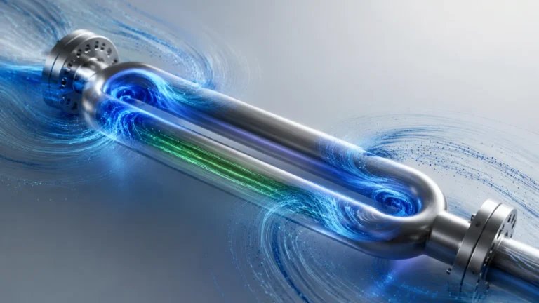
When no fluid is flowing, the vibration of the measuring tubes is symmetrical. As fluid enters the meter and moves through the vibrating tubes, it is forced to take on the vertical momentum of the tube's vibration. As the fluid moves toward the point of maximum vibration (the center of the loop), it resists the upward motion, pushing down on the tube. Conversely, as the fluid leaves the center and moves toward the outlet, it resists the slowing of its vertical motion, pushing up on the tube.
This creates a twisting effect, or a phase shift, between the inlet and outlet sides of the tube. Sensors located at the inlet and outlet measure this time delay ($Δt$). This phase shift is directly proportional to the mass flow rate. Because mass is measured directly, the meter is unaffected by changes in fluid viscosity, conductivity, or flow profile.
Simultaneous Density and Temperature Measurement
One of the primary advantages of this technology is its multivariable capability. In addition to mass flow, these meters provide:
1. Density: The resonant frequency at which the tubes vibrate depends on the total mass of the tubes and the fluid inside them. By measuring this frequency, the instrument can calculate the fluid's density in real-time.
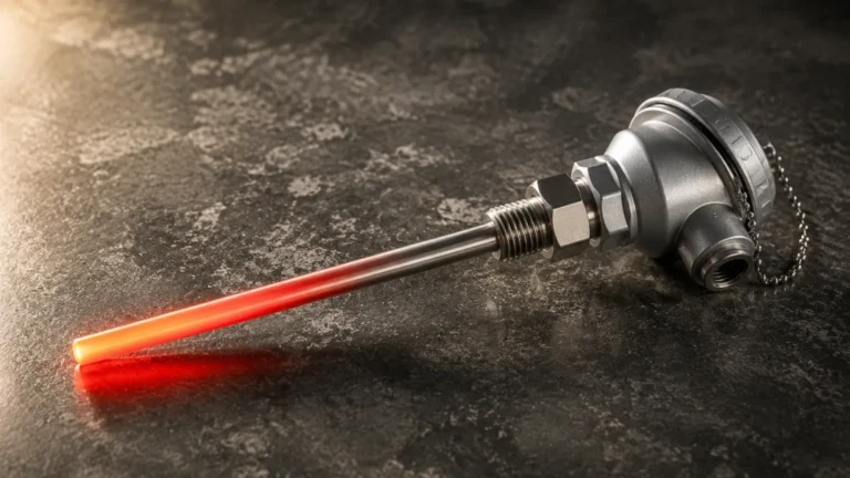
2. Temperature: Internal RTD (Resistance Temperature Detector) sensors monitor the tube temperature to compensate for changes in material elasticity and to provide a secondary process variable output.
Key Evaluation Criteria for Coriolis Mass Flow Meters
Selecting the right coriolis mass flow meter requires a balance between precision requirements, fluid characteristics, and budget constraints. Engineers should evaluate the following factors during the procurement phase.
Accuracy and Repeatability
Coriolis meters are among the most accurate flow instruments available. Typical liquid mass flow accuracy ranges from ±0.05% to ±0.1% of the flow rate. For gas applications, accuracy is generally lower, typically around ±0.25% to ±0.5%. It is important to distinguish between "percentage of rate" and "percentage of full scale," as coriolis meters maintain high accuracy over a wide turndown ratio (often 100:1 or better).
Tube Design: U-Shape vs. Straight Tube
The physical geometry of the measuring tubes impacts performance and maintenance:
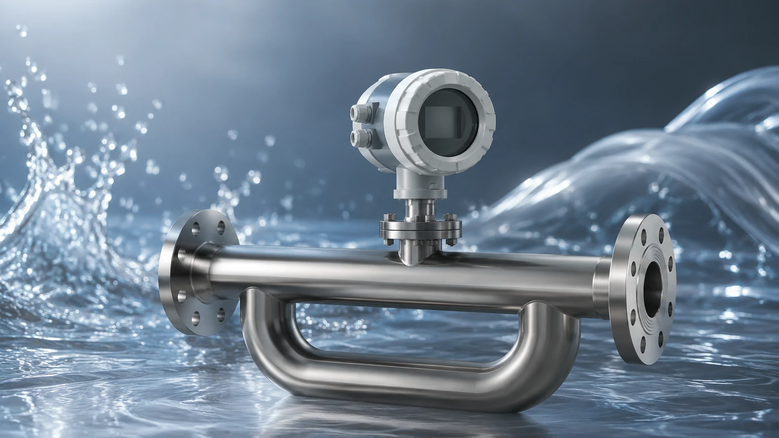
* U-Shaped Tubes: These are highly sensitive and offer the best accuracy and turndown ratios. However, they can be bulky and may trap air or sediment if not oriented correctly.
* Straight Tubes: These are easier to clean (piggable) and have a lower pressure drop. They are preferred for hygienic applications or fluids that tend to coat surfaces, though they may require more sophisticated compensation for thermal expansion.
Material Compatibility
The wetted parts must be compatible with the process fluid. Common materials include 316L Stainless Steel for general use, Hastelloy® C-22 for corrosive chemicals, and Tantalum for extremely aggressive acids. Choosing the wrong material can lead to stress corrosion cracking, especially given the high-frequency vibration of the tubes.
Practical Selection Table
The following table provides a general guideline for selecting meter characteristics based on common industrial requirements.
| Application Requirement | Recommended Feature | Rationale |
| :— | :— | :— |
| High Precision Custody Transfer | Dual U-Tube Design | Maximizes phase shift signal-to-noise ratio. |
| Sanitary / Food & Beverage | Straight-Tube 316L | Allows for CIP (Clean-In-Place) and prevents bacterial growth. |
| High Pressure (up to 350 bar / 5000 psi) | Thick-walled Alloy Tubes | Ensures structural integrity under extreme stress. |
| Entrained Gas (Slurries) | Advanced Digital Signal Processing | Compensates for "slug flow" and dampening effects. |
| Low Pressure Drop | Large Diameter Straight Tube | Minimizes energy loss in gravity-fed systems. |
Installation Considerations and Best Practices
While coriolis mass flow meters are robust, their reliance on high-frequency vibration makes them sensitive to certain installation environments. Proper mechanical integration is vital for maintaining the stated accuracy.
Support and Vibration Isolation
The meter should be securely mounted to rigid piping or supports. Because the meter operates on vibration, external vibrations from pumps or motors at similar frequencies can interfere with the measurement. Using flexible connectors is generally discouraged unless the meter itself is independently and rigidly supported to prevent it from "shaking" along with the pipe.
Orientation for Fluid Phases
Orientation is critical to ensure the tubes remain full and free of trapped gases or solids:
* Liquid Service: The tubes should point downward (in a "flag" or "U" position) to prevent gas bubbles from collecting in the sensor.
* Gas Service: The tubes should point upward to prevent condensate or liquids from pooling in the bottom of the tubes.
* Slurry Service: Vertical installation with upward flow is often preferred to ensure solids do not settle out and that the tubes remain self-draining.
Zero Calibration
After installation and under actual process conditions (temperature and pressure), a "zero trim" must be performed. This involves shutting off the flow completely while ensuring the tubes remain full of the process fluid. This calibrated zero point accounts for the specific mechanical stresses of the piping installation.
Limitations and Common Risks
Despite their versatility, coriolis mass flow meters are not a universal solution for every application. Understanding their limitations prevents costly misapplications.
1. Initial Cost: The capital expenditure for a coriolis meter is significantly higher than for electromagnetic or vortex meters. The ROI must be justified by the need for mass accuracy or density data.
2. Pressure Drop: U-tube designs can introduce a significant pressure drop in the system. In low-pressure gravity systems, this may reduce flow rates below acceptable levels.
3. Size and Weight: Large-diameter coriolis meters (above 200mm / 8 inches) are extremely heavy and require substantial structural support, making them difficult to retrofit into existing piping.
4. Entrained Air: While modern digital transmitters can handle small amounts of entrained gas, high percentages of air can cause the tubes to stop vibrating (stalling), leading to measurement errors or "frozen" outputs.
The Relationship Between Mass Flow and Level Measurement
In many process plants, mass flow and level measurement are used in tandem to provide a complete picture of inventory and process efficiency. For example, in a chemical reactor, a radar level meter or ultrasonic sensor provides the primary volume measurement, while a coriolis meter on the feed line ensures the exact mass of reactants is added.
Welk provides a comprehensive range of level measurement solutions that complement flow systems. By integrating accurate level data with mass flow inputs, operators can perform real-time mass balance calculations, which are essential for leak detection and yield optimization. For those exploring the broader spectrum of industrial sensors, reviewing the various technologies on the Main Page can help in designing a holistic measurement strategy.
Frequently Asked Questions (FAQ)
Q: Can coriolis meters measure the flow of gases?
A: Yes, but with caveats. Because gases have much lower density than liquids, the mass flow rate is lower, resulting in a weaker phase shift signal. This usually requires higher flow velocities and may result in lower accuracy compared to liquid applications.
Q: Do coriolis meters require straight pipe runs?
A: Unlike turbine or ultrasonic meters, coriolis meters are generally insensitive to flow profile disturbances. They do not require long straight runs of pipe upstream or downstream, which makes them ideal for compact skids.
Q: How long do these meters last?
A: Because there are no moving parts like bearings or gears to wear out, coriolis meters have a very long service life, often exceeding 10-15 years, provided the tubes are not eroded or corroded by the process fluid.
Q: Is periodic recalibration necessary?
A: While the electronic components are stable, mechanical changes (such as internal coating or erosion) can shift the calibration. Most industries perform a verification check every 1-2 years, though many modern meters include onboard diagnostics that can verify the "health" of the tubes without removing them from the line.
By adhering to these engineering principles and selection guidelines, B2B procurement teams and plant engineers can ensure that their investment in coriolis mass flow technology yields the precision and reliability required for modern industrial automation.