Radar Level Transmitter Working Principle
Radar Level Transmitter Working Principle: An Engineering Guide for Industrial Applications
In the landscape of industrial automation, accurate level measurement is critical for process safety, inventory management, and operational efficiency. Among the various technologies available, radar-based systems have emerged as the gold standard for challenging environments. Understanding the radar level transmitter working principle is essential for engineers and procurement specialists to select the right equipment for specific media and vessel geometries.
This guide explores the physics behind radar technology, compares different modulation techniques, and provides practical selection and installation criteria for Radar Level Meters.
Understanding the Fundamental Radar Level Transmitter Working Principle
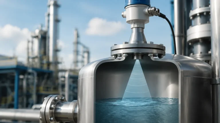
At its core, a radar level transmitter is a "top-down" direct measurement device. It operates by emitting electromagnetic waves (microwaves) from an antenna toward the surface of the material being measured. These waves travel through the vapor space, reflect off the surface of the medium, and return to the sensor's receiver.
The fundamental radar level transmitter working principle relies on the properties of electromagnetic waves, which travel at the speed of light (approximately 300,000 km/s). Because the speed of these waves is constant in a given medium, the distance to the material surface can be calculated by measuring the time it takes for the signal to complete its round trip. This is often referred to as Time of Flight (ToF).
The basic formula used by the transmitter's microprocessor is:
Distance = (Speed of Light × Transit Time) / 2
Once the distance to the product surface is known, the transmitter subtracts this value from the total tank height (the calibration zero point) to determine the actual level of the liquid or solid.
Pulse Radar vs. FMCW Technology
While the basic principle involves timing a signal, industrial radar level meters typically utilize one of two primary modulation techniques: Pulse Radar or Frequency Modulated Continuous Wave (FMCW).
1. Pulse Radar (Time of Flight)
Pulse radar transmitters emit a series of short-duration microwave pulses. The device measures the elapsed time between the emission of the pulse and the reception of the echo.
* Advantages: Lower power consumption, making it ideal for loop-powered (2-wire) installations.
* Best For: Simple liquid storage applications where extreme precision is not the primary concern.
2. Frequency Modulated Continuous Wave (FMCW)
FMCW radar does not send pulses; instead, it emits a continuous signal with a constantly changing frequency (a frequency sweep). When the reflected signal is received, it is compared to the signal being emitted at that exact moment. The difference in frequency (the "beat frequency") is directly proportional to the distance the signal has traveled.
* Advantages: Significantly higher accuracy, better signal-to-noise ratio, and superior ability to filter out false echoes caused by tank internals.
* Best For: Complex process vessels with agitators, steam, or turbulent surfaces.
The Role of Frequency in Radar Measurement
The frequency at which a radar level transmitter operates—measured in Gigahertz (GHz)—dictates its performance characteristics, specifically its beam angle and sensitivity.
* 6 GHz (C-Band): These lower-frequency radars are less affected by foam or heavy dust but require very large antennas to achieve a narrow beam. They are often used in older installations or specific heavy-foam applications.
* 26 GHz (K-Band): A versatile middle ground, 26 GHz radars offer a smaller antenna size and a narrower beam than 6 GHz models. They are widely used in chemical and water treatment sectors.
* 80 GHz (W-Band): The modern standard for high-precision measurement. 80 GHz radar level meters feature an extremely narrow beam angle (often as low as 3 degrees). This allows the signal to avoid internal obstructions like ladders or heating coils and provides exceptional accuracy in narrow or tall vessels.
Non-Contact Radar vs. Guided Wave Radar (GWR)
When evaluating the radar level transmitter working principle, it is important to distinguish between non-contact and contact-based (guided) systems.
Non-Contact Radar
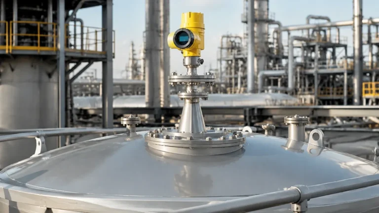
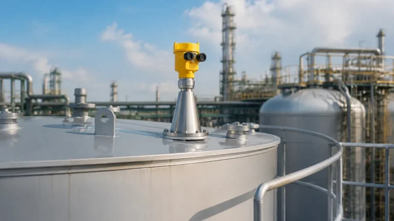
The antenna is mounted at the top of the tank and never touches the medium. This is ideal for corrosive, hygienic, or extremely hot materials where sensor degradation is a risk.
Guided Wave Radar (GWR)
GWR uses a physical probe (rod or cable) to guide the microwave signal to the surface. The signal travels along the probe, hits the medium, and reflects back.
* Efficiency: Because the signal is concentrated along the probe, GWR is highly effective for media with very low dielectric constants (like liquefied gases or oils) where a non-contact signal might dissipate.
* Interface Measurement: GWR is uniquely capable of measuring the interface between two liquids (e.g., oil and water).
Technical Selection Criteria
Choosing the correct radar level meter requires an analysis of the physical and chemical properties of the application. Use the following table as a preliminary selection guide:
| Feature | Non-Contact Radar (80 GHz) | Guided Wave Radar (GWR) | Pulse Radar (26 GHz) |
| :— | :— | :— | :— |
| Best Media | Liquids, Corrosives, Solids | Low Dielectric Liquids, Interfaces | Standard Liquids, Water |
| Accuracy | High (±1mm to ±2mm) | High (±2mm) | Moderate (±3mm to ±5mm) |
| Max Range | Up to 120m (394 ft) | Up to 75m (246 ft) | Up to 30m (98 ft) |
| Pressure Limit | Up to 160 bar | Up to 400 bar | Up to 40 bar |
| Temp. Limit | Up to 450°C (842°F) | Up to 450°C (842°F) | Up to 250°C (482°F) |
| Internal Obstacles | Excellent avoidance | Not affected (if probe is clear) | Moderate avoidance |

Installation Best Practices and Constraints
Even the most advanced radar level meter will fail if installed incorrectly. Engineers must consider the following geometric constraints:
1. The Dead Zone (Blocking Distance): Every radar has a minimum distance near the antenna where measurement is impossible. Ensure the maximum fill level of the tank does not enter this zone (typically 50mm to 200mm depending on the model).
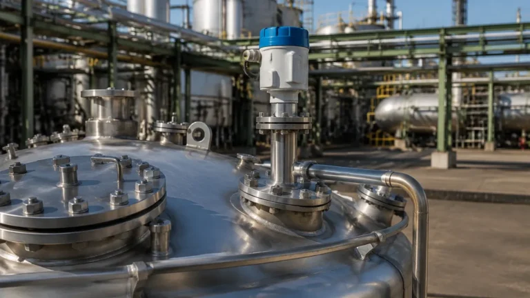
2. Nozzle Dimensions: The nozzle height should be kept as short as possible. If the nozzle is too long or narrow, the radar signal may reflect off the nozzle walls before even entering the tank, creating "ringing" or noise.
3. Beam Spread: Calculate the beam diameter at the bottom of the tank. The formula is: `Diameter = 2 × Distance × tan(Beam Angle / 2)`. Ensure no ladders, pipes, or agitators fall within this cone.
4. Mounting Position: Never mount a radar transmitter in the center of a domed tank, as this can cause multiple reflections to converge at the sensor. Ideally, mount the device at 1/3 of the tank radius from the wall.
5. Avoid the Inflow: Do not install the sensor directly above the tank inlet, as the falling stream of material will interfere with the signal reflections.
Limitations and Application Risks
While highly versatile, radar technology has specific limitations:
* Dielectric Constant (εr): The reflectively of a material depends on its dielectric constant. Materials with high εr (like water, εr ≈ 80) reflect signals strongly. Materials with low εr (like hydrocarbons or dry powders, εr < 2) reflect very little energy, requiring high-sensitivity 80 GHz units or GWR.
* Heavy Foam: Dense, thick foam can absorb the microwave signal entirely, leading to a "loss of echo" error. In these cases, low-frequency 6 GHz radar or hydrostatic pressure transmitters may be preferred.
* Heavy Condensation/Icing: While radar can penetrate some vapor, heavy buildup on the antenna lens can attenuate the signal. Many modern Radar Level Meters utilize PTFE or PEEK lenses with "drip-off" designs to mitigate this.
Frequently Asked Questions (FAQ)
Q: Can radar level transmitters measure solids?
A: Yes. However, solids often have an angle of repose (a sloped surface). 80 GHz radars are preferred here because their narrow beam can be aimed at a specific point on the slope, and their high frequency handles the diffuse reflections from uneven surfaces better than lower-frequency models.
Q: Does vacuum affect radar measurement?
A: No. Unlike ultrasonic sensors, which require a medium (air) to transmit sound, radar uses electromagnetic waves that travel perfectly through a vacuum. This makes radar ideal for vacuum distillation columns.
Q: How do I handle agitators in the tank?
A: Use a transmitter with FMCW technology and advanced "False Echo Suppression" software. The transmitter can be programmed to recognize the fixed position of the agitator blades and ignore those specific reflections.
Q: What is the maintenance requirement for a radar meter?
A: Because non-contact radar has no moving parts and does not touch the media, maintenance is minimal. Periodic checks of the antenna lens for heavy coating and verifying the electronic diagnostics are usually sufficient.
Conclusion
Understanding the radar level transmitter working principle allows process engineers to move beyond guesswork and implement robust, reliable measurement solutions. By considering the modulation type (Pulse vs. FMCW), the frequency (26 GHz vs. 80 GHz), and the dielectric properties of the media, facilities can significantly reduce downtime and prevent overfill incidents. For high-stakes industrial environments, the precision and non-mechanical nature of radar technology offer a clear advantage over traditional float or pressure-based systems.