How Radar Level Transmitter Works
How Radar Level Transmitter Works: A Comprehensive Engineering Guide
In the landscape of industrial automation, precise level measurement is critical for inventory management, process safety, and operational efficiency. Among the various technologies available, radar-based systems have emerged as the gold standard for challenging environments. Understanding how radar level transmitter works is essential for engineers and procurement specialists who must select the most reliable instrumentation for chemical tanks, water treatment facilities, and oil and gas storage.
Radar level measurement is a non-contact or contact-based technology that uses electromagnetic waves to determine the distance to a product surface. Unlike ultrasonic sensors, which rely on sound waves and are affected by air temperature and pressure, radar waves travel at the speed of light and are largely immune to environmental fluctuations. This article provides a technical deep dive into the principles, selection criteria, and installation requirements for modern Radar Level Meters.
Measurement Principles: Time of Flight and FMCW
To understand how radar level transmitter works, one must first distinguish between the two primary methods of signal modulation: Pulse Radar and Frequency Modulated Continuous Wave (FMCW).
1. Pulse Radar (Time of Flight)
Pulse radar transmitters operate by emitting a short microwave pulse toward the medium surface. The signal travels through the tank's headspace, hits the surface of the liquid or solid, and reflects back to the sensor’s antenna. The instrument measures the "Time of Flight" (ToF)—the total time elapsed between the emission and the reception of the pulse.
Since the speed of electromagnetic waves (c) is a known constant (~300,000 km/s), the distance (D) can be calculated using the formula:
D = (c × t) / 2
where *t* is the measured time. The level of the material is then derived by subtracting the distance (D) from the total tank height (H).
2. Frequency Modulated Continuous Wave (FMCW)
FMCW is the preferred technology for high-precision applications. Instead of sending discrete pulses, the transmitter emits a continuous signal with a frequency that changes linearly over time (a frequency sweep). When the reflected signal returns, it is compared to the signal currently being emitted. The difference in frequency (the "beat frequency") is directly proportional to the distance the signal has traveled. This method allows for much higher resolution and better signal-to-noise ratios, especially in turbulent conditions.
Frequency Bands and Their Impact
The frequency at which a radar level meter operates significantly influences its performance. Welk and other industrial manufacturers typically offer devices across three main bands:
* 6 GHz (C-Band): Known for its ability to penetrate heavy foam and steam. It has a wider beam angle, making it less suitable for narrow tanks with internal obstructions.
* 26 GHz (K-Band): The industry workhorse. It offers a balance between a focused beam and the ability to handle moderate dust or vapor. It is widely used in chemical and water treatment applications.
* 80 GHz (W-Band): The latest advancement in radar technology. With a very short wavelength, 80 GHz radar produces a extremely narrow beam (often as small as 3°). This allows the signal to avoid internal tank structures like ladders or agitators and provides millimeter-level accuracy.
How Radar Level Transmitter Works: The Step-by-Step Process
Beyond the basic physics, the internal logic of a radar level transmitter involves several sophisticated stages:
1. Signal Generation: The electronics module generates a high-frequency microwave signal.
2. Emission: The antenna (horn, lens, or rod) shapes the signal into a beam and directs it toward the target.
3. Reflection: When the wave hits a medium with a different dielectric constant (εr) than the air/gas in the tank, a portion of the energy is reflected. Materials with high dielectric constants (like water, εr ≈ 80) reflect strongly, while hydrocarbons (εr ≈ 2) reflect weakly.
4. Reception and Processing: The antenna captures the reflected echo. The transmitter’s microprocessor uses complex algorithms (such as Fast Fourier Transform or False Echo Suppression) to distinguish the true level from echoes caused by tank walls or mixers.
5. Output: The processed distance is converted into a standardized industrial signal, typically 4-20mA with HART, Modbus, or Profibus, for integration into a PLC or DCS.
Practical Selection Criteria
When choosing between different Radar Level Meters, engineers must evaluate the physical properties of the media and the vessel geometry. The following table provides a guideline for technology selection based on application needs.
Selection Table: Radar Technology vs. Application
| Application Characteristic | Recommended Radar Type | Reasoning |
| :— | :— | :— |
| High Dielectric Liquids (Water) | 26 GHz or 80 GHz | Strong reflections allow for high accuracy and smaller antennas. |
| Low Dielectric Liquids (Oil/Fuel) | Guided Wave Radar (GWR) | The probe guides the signal, minimizing energy loss in low-reflectivity media. |
| Solid Powders/Granules | 80 GHz FMCW | Narrow beam avoids wall interference; high frequency handles uneven surfaces. |
| Heavy Foam/Agitation | 6 GHz or GWR | Lower frequencies or physical contact (GWR) penetrate foam more effectively. |
| Narrow Tanks with Obstructions | 80 GHz | The narrow beam angle (3°-4°) bypasses internal structures. |
| Corrosive Chemicals | PTFE-coated Non-contact | Prevents chemical attack on the sensor while maintaining hygiene. |
Installation Considerations and Constraints
Even the most advanced radar transmitter will fail if installed incorrectly. To ensure the principles of how radar level transmitter works are optimized in the field, follow these engineering constraints:
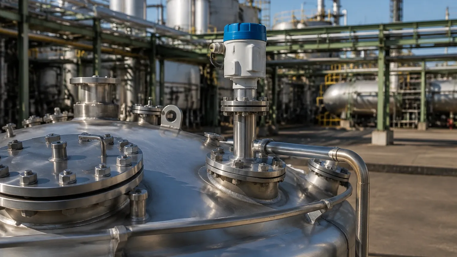
* Nozzle Height and Diameter: The antenna should ideally extend slightly beyond the mounting nozzle to prevent "ringing" or internal reflections within the neck. For 80 GHz units, nozzle interference is less critical due to the narrow beam.
* The 1/10th Rule: Generally, the sensor should be mounted at a distance from the tank wall equal to at least 1/10th of the tank height to avoid side-wall interference.
* Obstruction Clearance: Ensure the signal path is clear of ladders, heating coils, and fill streams. If an obstruction is unavoidable, use the software’s "False Echo Mapping" feature to tell the transmitter to ignore that specific distance.
* Orientation: For solid materials, an adjustable flange (aiming kit) is often required to point the radar at the angle of repose to maximize signal return.
Limitations and Application Risks
While radar is highly versatile, it is not a universal solution for every scenario. Engineers should be aware of the following risks:
1. Dielectric Constant Limits: If a liquid has a dielectric constant below 1.4, non-contact radar may struggle to detect the surface. In these cases, Guided Wave Radar (GWR) or a stilling well is required.
2. Heavy Vacuum or High Pressure: While radar works in a vacuum (unlike ultrasonic), extreme pressures can change the vapor space's density, slightly affecting the speed of light and requiring a correction factor in high-precision applications.
3. Conductive Dust Buildup: In solid applications, if conductive dust coats the antenna lens, it can attenuate the signal. Many modern 80 GHz units include an air purge connection to keep the lens clean.
Comparison: Radar vs. Other Technologies
| Feature | Radar Level Meters | Ultrasonic Sensors | Hydrostatic Transmitters |
| :— | :— | :— | :— |
| Contact Type | Non-contact (mostly) | Non-contact | Contact (Submerged) |
| Accuracy | High (±1mm to ±3mm) | Moderate (±0.25% of range) | Moderate (±0.1% to 0.5%) |
| Vapor/Steam Impact | Negligible | High | None |
| Price | Higher | Lower | Moderate |
| Maintenance | Low | Low | Moderate (clogging risk) |
Frequently Asked Questions (FAQ)
Q: Does the tank pressure affect how radar level transmitter works?
A: Generally, no. Radar uses electromagnetic waves which do not require a medium to travel. However, at extremely high pressures, the dielectric constant of the gas phase may change slightly, necessitating a small compensation for custody-transfer grade accuracy.
Q: Can radar measure the interface between two liquids?
A: Yes, but this typically requires Guided Wave Radar. The signal reflects off the upper liquid (low dielectric) and then off the lower liquid (high dielectric), allowing the transmitter to calculate both the total level and the interface level.
Q: What is the maximum range for industrial radar?
A: Modern Radar Level Meters can measure distances up to 30 meters (approx. 100 ft) for liquids and up to 120 meters (approx. 393 ft) for solids in large silos.
Q: How do I handle heavy turbulence in a mixing tank?
A: Use an FMCW radar with a high update rate and apply software damping. Alternatively, installing the radar inside a bypass pipe or a stilling well will provide a calm surface for measurement.
Conclusion
Understanding how radar level transmitter works—from the fundamental physics of Time of Flight to the nuances of frequency selection—allows industrial operators to implement more robust control systems. By selecting the appropriate frequency and following strict installation guidelines, radar technology provides a maintenance-free, high-accuracy solution for even the most demanding process conditions. For international buyers, confirming the dielectric constant of the media and the internal geometry of the vessel remains the most critical step in ensuring equipment longevity and performance.