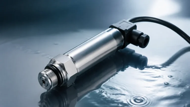
Turbidity Monitors
Turbidity Monitors
In industrial process control and environmental monitoring, the clarity of a liquid is often as critical as its chemical composition. Turbidity monitors are the primary instruments used to quantify this clarity by measuring the loss of transparency caused by suspended particulate matter. Whether in municipal water treatment, chemical processing, or food and beverage production, understanding the concentration of suspended solids is essential for maintaining product quality and regulatory compliance.
While level measurement instruments, such as those found on the Main Page of industrial instrumentation providers, manage the volume and containment of fluids, turbidity monitors provide the analytical data necessary to understand the internal state of the process media. This article explores the principles, selection criteria, and installation requirements for industrial turbidity monitoring systems.
Understanding Turbidity Measurement Principles
Turbidity is not a direct measurement of the weight of suspended solids; rather, it is an optical property. When light passes through a liquid containing suspended particles, the particles scatter and absorb the light. Turbidity monitors measure this interaction using several distinct optical methods.
Nephelometry (90-degree Scattering)
Nephelometry is the most common method for measuring low to medium turbidity levels. According to international standards like ISO 7027 and US EPA 180.1, a light source (typically an LED or tungsten lamp) is directed into the sample. A detector is positioned at a 90-degree angle to the light beam. As particles pass through the beam, they scatter light toward the detector. The intensity of the scattered light is proportional to the concentration of particles. This method is highly sensitive and is the standard for drinking water applications.
Transmission (Attenuation)
In transmission-based measurement, the light source and the detector are aligned 180 degrees from each other. The monitor measures the decrease in light intensity as it travels through a fixed path length of the sample. This method is more suitable for high-turbidity applications where the concentration of solids is so high that 90-degree scattering becomes non-linear due to multiple scattering events.
Backscattering
Backscattering monitors position the light source and detector in close proximity, often within the same probe head. The detector measures light reflected back at an angle greater than 90 degrees. This technology is primarily used in very high-solids applications, such as sludge density monitoring in wastewater treatment or concentrated chemical slurries.
Ratio Method
Advanced turbidity monitors often use a "ratio" design, which incorporates multiple detectors at different angles (e.g., 90 degrees, forward scatter, and transmitted). By calculating the ratio of these signals, the instrument can compensate for color interference and fluctuations in light source intensity, providing a more stable and accurate reading across varying process conditions.
Key Technologies in Modern Turbidity Monitors
The choice of light source and sensing geometry defines the application range of the monitor. Engineers must distinguish between the two primary regulatory standards:
1. ISO 7027 (Infrared): Uses a Near-Infrared (NIR) LED, typically around 860 nm. This wavelength is invisible to the human eye and is effective at minimizing interference from the color of the liquid. It is the preferred standard in Europe and for many industrial wastewater applications.
2. US EPA 180.1 (White Light): Uses a tungsten filament lamp. This light source has a broad spectrum and is highly sensitive to very small particles, making it the standard for monitoring potable water in the United States.
Selection Criteria for Industrial Applications
Selecting the correct turbidity monitor requires an analysis of the process environment and the physical properties of the liquid. The following table provides a comparison of common configurations:
| Feature | Nephelometric (90°) | Absorption (180°) | Backscatter |
| :— | :— | :— | :— |
| Measurement Range | 0–1,000 NTU | 100–4,000 FAU | 0–100 g/L (Sludge) |
| Primary Use Case | Drinking water, filtered water | Raw water, process liquids | Sludge, high-solids waste |
| Sensitivity | Very High | Moderate | Low |
| Color Interference | High (unless NIR used) | Moderate | Low |
| Typical Mounting | Flow cell / Bypass | In-line / Immersion | Immersion probe |
Evaluation Factors
* Measurement Range: Units are typically expressed in NTU (Nephelometric Turbidity Units), FNU (Formazin Nephelometric Units), or mg/L for suspended solids. Ensure the instrument's range covers both normal operation and potential process upsets.
* Process Temperature and Pressure: Standard immersion probes are often rated up to 50°C (122°F), but high-temperature versions for chemical processes can handle up to 100°C or more. Pressure ratings must match the piping or vessel specifications.
* Chemical Compatibility: The wetted parts—including the sensor body (316L stainless steel, PVC, or PEEK) and the optical windows (Sapphire or Quartz)—must be resistant to the process media.
* Maintenance Requirements: In applications prone to scaling or biological growth, sensors with integrated cleaning systems (wipers or ultrasonic cleaners) are essential to prevent "drift" in readings.
Installation Best Practices and Considerations
The accuracy of a turbidity monitor is highly dependent on its installation. Unlike level measurement, where a sensor like a radar meter on the Main Page can often be mounted with minimal contact, turbidity sensors are usually in direct contact with the flow.
Air Bubble Management
Air bubbles are the most common source of error in turbidity measurement. To an optical sensor, a bubble looks like a solid particle, leading to falsely high readings.
* Bypass Installation: Use a flow cell with an integrated de-bubbler or "bubble trap" to allow air to escape before the water reaches the sensor.
* Orientation: When installing in-line, place the sensor on the side of the pipe (3 o'clock or 9 o'clock position). Avoid the top (where air collects) and the bottom (where sediment settles).
Flow Velocity
Maintain a consistent flow rate. If the flow is too slow, particles may settle out of suspension, leading to low readings. If the flow is too fast, it may create cavitation or turbulence that introduces bubbles. A flow velocity between 0.5 m/s and 2.0 m/s is generally recommended for in-line sensors.
Ambient Light Interference
Ensure that the sensor is shielded from direct sunlight or strong artificial light, especially if using open-channel immersion probes. Most modern sensors use pulsed light and digital filtering to reject ambient light, but physical shielding remains a best practice for high-precision applications.

Limitations and Maintenance Requirements
Despite their sophistication, turbidity monitors have inherent limitations that must be managed through regular maintenance and calibration.
1. Fouling: Even a thin film of oil, algae, or mineral scale on the optical window will significantly degrade accuracy. Automatic cleaning cycles reduce but do not eliminate the need for manual inspection.
2. Particle Size and Shape: Turbidity is a measure of light scattering, which is affected by particle size. Two samples with the same mass concentration of solids but different particle sizes will yield different NTU values. Calibration should always be performed using the actual process media if mass concentration (mg/L) is the desired output.
3. Calibration Standards: Instruments are typically calibrated using Formazin, a synthetic polymer. Because Formazin is toxic, many operators use stabilized Formazin or secondary standards (beads) for routine verification.
Regular Maintenance Checklist
* Monthly: Inspect optical windows for fouling; verify readings against a portable lab meter.
* Quarterly: Clean the sensor head manually; check O-rings and seals for wear.
* Annually: Perform a full multi-point calibration using fresh Formazin standards; replace wipers or cleaning blades if applicable.
Integrating Turbidity with Level Measurement
In many industrial setups, turbidity monitoring is part of a broader automation strategy that includes level measurement. For instance, in a sedimentation tank, a hydrostatic level transmitter or an ultrasonic sensor (technologies detailed on the Main Page) is used to monitor the liquid level, while a turbidity monitor at the effluent weir ensures that only clear water is discharged.
In sludge blanket applications, the level sensor tracks the height of the settled solids, while the turbidity probe monitors the density of the sludge being pumped out. Integrating these data points into a single PLC (Programmable Logic Controller) allows for fully automated process optimization, reducing chemical usage and energy costs.
Frequently Asked Questions (FAQs)
Q: What is the difference between NTU and FNU?
A: Both units are numerically equivalent when measuring Formazin. However, NTU (Nephelometric Turbidity Units) is generally used when referring to measurements made with a white light source (EPA 180.1), while FNU (Formazin Nephelometric Units) refers to measurements made with an infrared light source (ISO 7027).
Q: Can a turbidity monitor measure dissolved substances?
A: No. Turbidity monitors only detect suspended solids. Dissolved substances, such as salt or sugar, do not scatter light in the same way and require different analytical methods like conductivity or refractometry.
Q: How often should I calibrate my turbidity monitor?
A: For regulatory compliance in drinking water, daily or weekly verification is common. For general industrial use, a monthly check and quarterly calibration are usually sufficient, provided the sensor has an automatic cleaning mechanism.
Q: Does the color of the liquid affect the reading?
A: Yes, if using a white light sensor. Darker liquids absorb more light, which can artificially lower the scattered light signal. Using an infrared (NIR) light source or a ratio-based sensor significantly reduces this interference.
Conclusion
Turbidity monitors are indispensable tools for ensuring process efficiency and environmental safety. By understanding the optical principles of nephelometry and transmission, and by implementing rigorous installation and maintenance protocols, industrial operators can achieve reliable, real-time insights into water quality. When combined with robust level measurement solutions, these instruments form the backbone of modern industrial fluid management. For more information on the level measurement components that complement these analytical systems, visit the Main Page to explore professional-grade industrial instrumentation.