How to Test a Pressure Transducer
How to Test a Pressure Transducer
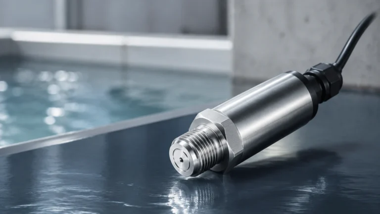
In industrial process control, pressure transducers are the primary sensory organs of a system. They convert mechanical pressure into an electrical signal, enabling the monitoring of gases, liquids, and vapors. For many engineers and technicians, the pressure transducer is also a critical component in hydrostatic level measurement, where the weight of a liquid column is translated into a depth reading. When a system reports erratic data or fails to respond, knowing how to test a pressure transducer becomes a vital skill for maintaining uptime and ensuring safety.
This guide provides a comprehensive technical framework for evaluating the health and accuracy of pressure transducers, specifically focusing on those used in industrial automation and level measurement applications. By following standardized testing procedures, facilities can distinguish between a faulty sensor, a wiring issue, or a calibration drift.
Understanding Pressure Transducer Principles
Before initiating a test, it is essential to understand the underlying technology of the device. Most modern industrial transducers, such as those manufactured by Welk, utilize one of three primary measurement principles. Understanding these principles helps in identifying specific failure modes during testing.
Piezoresistive Sensors
These sensors utilize a micromachined silicon diaphragm with integrated resistors. When pressure is applied, the diaphragm flexes, changing the resistance of the bridge circuit. This technology is highly sensitive and common in hydrostatic level transmitters. However, these sensors are sensitive to temperature fluctuations, which is why high-quality units include internal temperature compensation.
Capacitive Sensors
Capacitive transducers measure the change in electrical capacitance between a sensing diaphragm and a rigid metal plate. As pressure moves the diaphragm, the gap changes, altering the capacitance. These are known for their robustness and high overpressure resistance, making them ideal for harsh industrial environments where pressure spikes are common.
Strain Gauge Sensors
Strain gauge transducers involve bonding a metal foil or thin-film gauge to a diaphragm. As the diaphragm deforms under pressure, the gauge stretches or compresses, changing its electrical resistance. These are often used in high-pressure applications where durability is the priority.
Regardless of the internal technology, the output is typically standardized to an industrial signal: 4-20 mA (current loop), 0-5 VDC, or 0-10 VDC. Testing involves verifying that the relationship between the applied physical pressure and this electrical output remains within the manufacturer's specified tolerance.
Essential Tools for Testing
To perform an accurate field or bench test, you will need the following equipment:
1. Digital Multimeter (DMM): Capable of measuring DC voltage and milliamps (mA) with high precision (at least 4.5 digits recommended).
2. DC Power Supply: Usually 24V DC, which is the standard for most industrial loops.
3. Pressure Source: A regulated hand pump or a deadweight tester capable of reaching the transducer's full-scale range.
4. Reference Gauge: A calibrated digital or analog gauge with a higher accuracy class than the transducer under test (typically 3:1 or 4:1 accuracy ratio).
5. Resistors: A 250-ohm resistor may be necessary if you are testing a 4-20 mA signal and need to convert it to a 1-5V signal for certain data loggers.
Step-by-Step: How to Test a Pressure Transducer
Testing should be performed in a controlled environment whenever possible, but these steps can be adapted for field troubleshooting.
1. Visual and Mechanical Inspection
Before applying power, inspect the housing for physical damage. Check the process connection for clogs or corrosion. For submersible level transducers, inspect the cable jacket for nicks or swelling, as moisture ingress into the vent tube is a common cause of failure. Ensure the diaphragm is not dented or coated with debris; even a small amount of buildup can cause significant measurement errors.
2. Electrical Continuity and Isolation Test
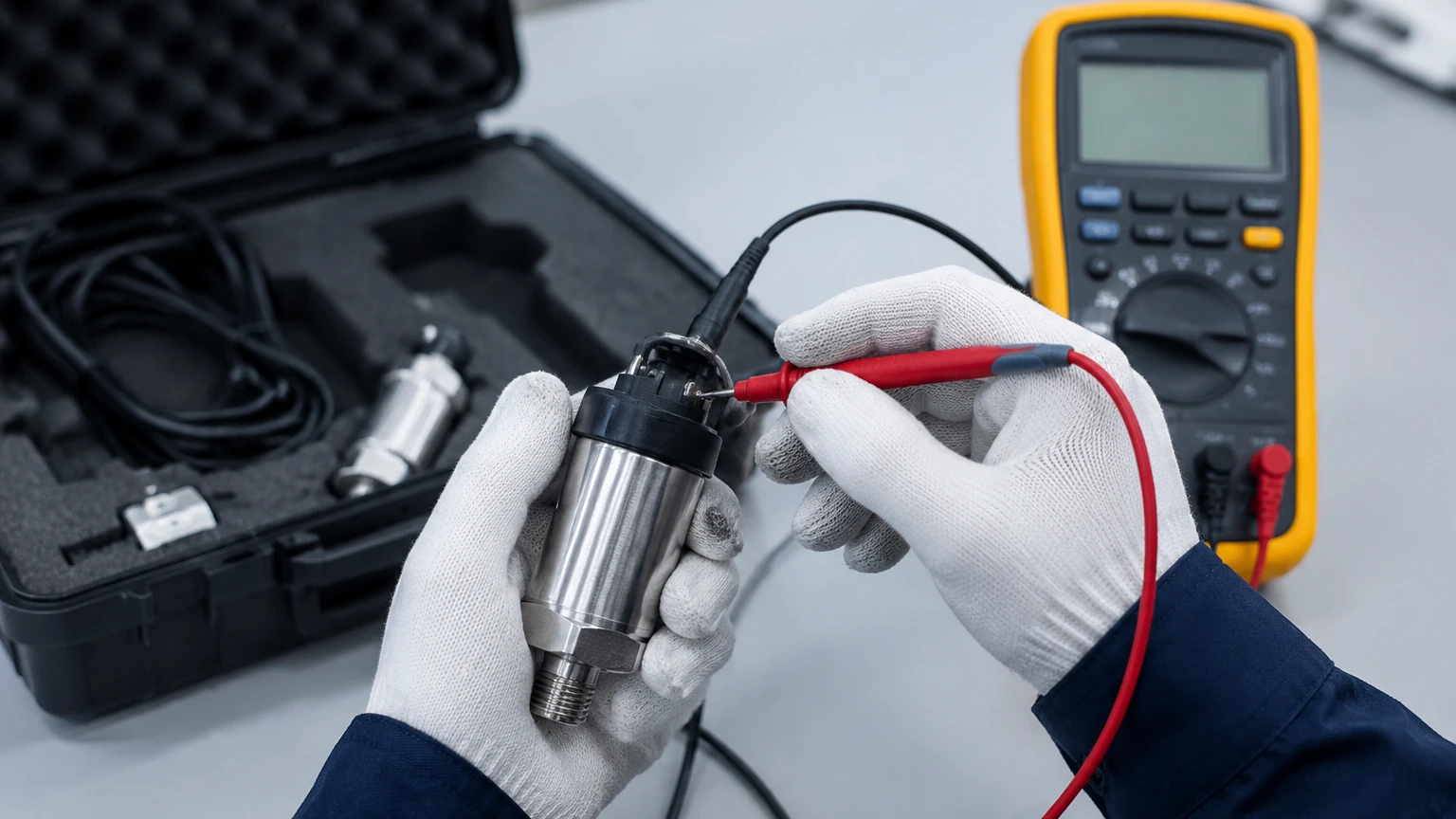
With the power off, use the multimeter to check for continuity between the transducer leads.
* Isolation: Check the resistance between each lead and the transducer housing. It should be infinite (typically >100 MΩ). If there is low resistance, the internal insulation has failed, and the unit must be replaced.
* Bridge Resistance: For millivolt output sensors, check the input and output resistance of the bridge circuit against the manufacturer's datasheet.
3. Zero-Point Verification
The "Zero Point" is the electrical output when no pressure is applied (atmospheric pressure for gauge sensors).
* Connect the transducer to a stable power supply.
* For a 4-20 mA sensor, the output should be exactly 4.00 mA.
* For a 0-10 V sensor, the output should be 0.00 V.
* If the reading is 4.05 mA or 3.95 mA, the sensor has a "zero shift." Small shifts can often be calibrated out, but a shift larger than 5% of the span usually indicates a damaged diaphragm.
4. Full-Scale Span Test
This step verifies the transducer's ability to measure at the top of its range.
* Connect the pressure source (hand pump) and the reference gauge to the transducer.
* Slowly increase the pressure to the maximum rated limit of the transducer.
* At full pressure, a 4-20 mA sensor should output 20.00 mA.
* Compare the reading to the reference gauge. If the transducer reads 19.5 mA when the reference gauge shows full pressure, the span is out of calibration.
5. Linearity and Hysteresis Check
A transducer might be accurate at 0% and 100% but inaccurate in the middle. To test this, perform a 5-point check:
1. 0% Pressure: Target 4 mA.
2. 25% Pressure: Target 8 mA.
3. 50% Pressure: Target 12 mA.
4. 75% Pressure: Target 16 mA.
5. 100% Pressure: Target 20 mA.
Repeat these steps while decreasing the pressure to check for hysteresis—the difference in readings when approaching a point from above versus below. Excessive hysteresis usually indicates mechanical fatigue in the sensing element.
Selection Criteria for Pressure Transducers
Choosing the right instrument prevents many of the issues that lead to frequent testing. The following table compares different transducer configurations for industrial level and pressure applications.
| Feature | Submersible Hydrostatic | Gauge Pressure Transducer | Absolute Pressure Transducer |
| :— | :— | :— | :— |
| Primary Use | Liquid level in tanks/wells | Pipe pressure, vented tanks | Vacuum systems, barometric |
| Reference | Atmospheric (via vent tube) | Atmospheric (via port) | Vacuum (sealed internal) |
| Common Range | 0–1 mH2O to 0–200 mH2O | 0–0.1 bar to 0–1000 bar | 0–1 bar to 0–50 bar |
| Installation | Suspended in liquid | Threaded into process line | Threaded into process line |
| Key Testing Focus | Vent tube moisture/clogs | Diaphragm buildup | Seal integrity |
For engineers looking to source high-reliability instruments, it is helpful to Review product options and application support to ensure the selected hardware matches the chemical and physical demands of the process.
Installation Considerations to Prevent Failure
Often, what appears to be a faulty transducer is actually an installation error. When troubleshooting, verify the following:
* Mounting Orientation: Some low-pressure transducers are sensitive to orientation due to the weight of the internal oil fill. If a sensor is tested horizontally but installed vertically, a small zero shift may occur.
* Pressure Snubbers: In systems with rapid valve closures (water hammer), pressure spikes can instantly destroy a diaphragm. If you find multiple failed transducers with "stretched" diaphragms, install a snubber to dampen the shocks.
* Ventilation: For gauge pressure sensors, the back of the diaphragm must be vented to the atmosphere. If the vent is blocked, the sensor will react to changes in barometric pressure, leading to inaccurate level readings.
* Temperature Limits: Ensure the process temperature does not exceed the compensated range of the sensor (typically -20°C to +80°C for standard units). High-temperature applications require siphons or cooling towers.
Limitations of Field Testing
While field testing with a hand pump is excellent for troubleshooting, it has limitations:
* Accuracy: Field reference gauges are rarely as accurate as laboratory-grade deadweight testers.
* Environment: Temperature and humidity fluctuations in the field can introduce variables that make precision calibration difficult.
* Documentation: For ISO-regulated industries, field tests may not suffice for official certification. In these cases, the transducer should be sent to a certified metrology lab.
Frequently Asked Questions (FAQs)
Q: Why does my pressure transducer read 0 mA?
A: A 0 mA reading usually indicates an open circuit. Check for broken wires, a blown fuse in the PLC input card, or a dead power supply. A functioning 4-20 mA sensor will always output at least 4 mA even at zero pressure.
Q: Can I test a pressure transducer with just a multimeter?
A: You can check the electrical health (continuity and zero point), but you cannot verify accuracy or linearity without a known pressure source and a reference gauge.
Q: What is the difference between a pressure transmitter and a transducer?
A: In common industrial usage, a *transducer* provides a low-level signal (like mV or unconditioned voltage), while a *transmitter* provides a conditioned high-level signal (like 4-20 mA) suitable for long-distance transmission. However, the terms are often used interchangeably.
Q: How often should I test my transducers?
A: For critical safety or billing applications, annual testing is standard. For general process monitoring, testing every 24 months or when erratic behavior is observed is usually sufficient.
Conclusion
Mastering how to test a pressure transducer allows maintenance teams to move from reactive repairs to proactive optimization. By understanding the piezoresistive or capacitive principles at play and utilizing a disciplined 5-point testing methodology, you can ensure your level measurement and process control systems remain accurate. For robust industrial applications, selecting high-quality hardware from a professional manufacturer like Welk ensures that the device is built to withstand the rigors of the field, reducing the frequency of required interventions. Always consult the specific technical manual for your model before performing adjustments to ensure compliance with factory specifications.