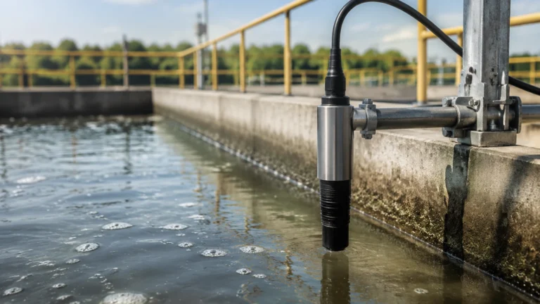
Thermal Flow Sensors
Thermal Flow Sensors
Thermal flow sensors, often referred to as thermal mass flow meters (TMFMs), represent a critical technology in the field of industrial process control. Unlike volumetric flow meters that require additional pressure and temperature compensation to calculate mass flow, thermal flow sensors measure the mass flow rate of fluids—primarily gases—directly based on the heat transfer characteristics of the medium. This capability makes them indispensable in applications ranging from compressed air management to complex chemical processing and wastewater treatment.
For engineers and facility managers, understanding the nuances of thermal flow sensors is essential for optimizing system efficiency and ensuring the longevity of measurement instrumentation. As a professional manufacturer of industrial level measurement instruments, Welk provides a comprehensive perspective on how flow and level data integrate to provide a complete picture of industrial automation processes. To explore a full range of instrumentation solutions, including radar and ultrasonic systems, you may visit the Main Page.
Understanding Thermal Mass Flow Measurement Principles
The operation of thermal flow sensors is rooted in the laws of thermodynamics, specifically the principle that a moving fluid will absorb heat from a heated surface in a manner proportional to its mass flow rate. In most industrial configurations, the sensor consists of two Resistance Temperature Detectors (RTDs). One RTD acts as a reference sensor, measuring the ambient temperature of the fluid, while the second RTD serves as the active heating element.
There are two primary methods used to translate this heat transfer into a flow measurement:
1. Constant Temperature Differential
In this mode, the electronic circuit maintains a constant temperature difference (typically denoted as ΔT) between the heated sensor and the reference sensor. As the mass flow rate increases, the fluid carries more heat away from the heated sensor. To maintain the constant ΔT, the instrument must increase the electrical power supplied to the heater. This power consumption is directly proportional to the mass flow rate of the gas.
2. Constant Power (Constant Current)
In this alternative method, a fixed amount of electrical power is supplied to the heated sensor. As the fluid flows past the sensor, the temperature difference between the heated probe and the reference probe changes. At higher flow rates, the cooling effect is greater, resulting in a smaller ΔT. The mass flow rate is then calculated as a function of this temperature differential.
Because these sensors measure heat transfer, they are naturally sensitive to the "thermal mass" of the fluid. This is why they provide a direct mass flow reading (e.g., kg/h or Nm³/h) without needing external pressure or temperature transmitters, provided the gas composition remains constant.
Key Components and Construction
Industrial thermal flow sensors are designed to withstand harsh environments, often featuring robust materials and sophisticated electronics. The primary components include:
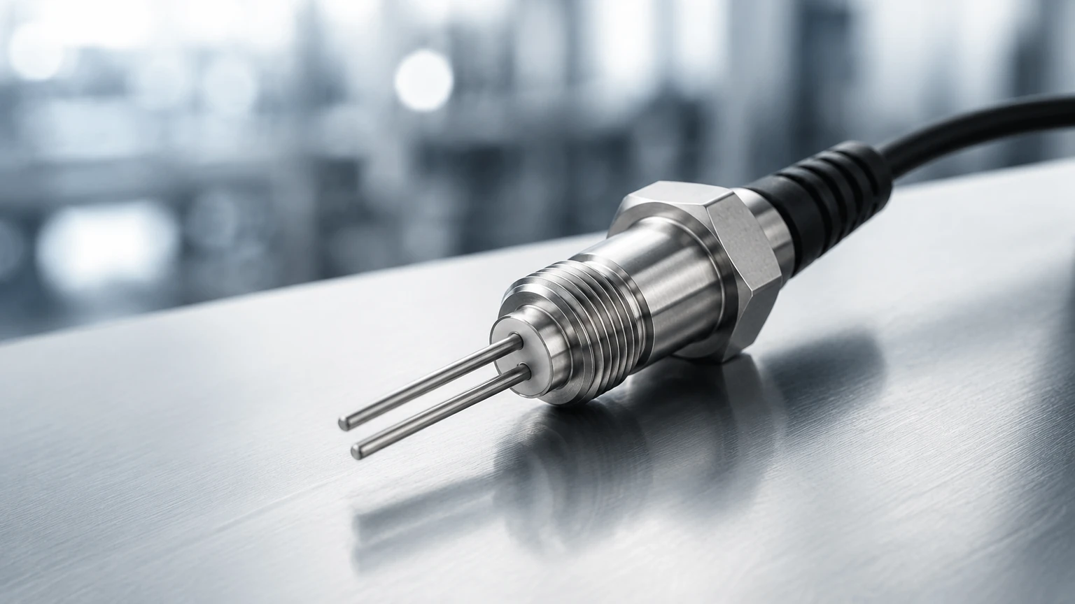
* Sensing Elements: Typically constructed from Platinum (such as PT100 or PT1000) encased in protective sheaths of stainless steel (316L) or high-performance alloys like Hastelloy for corrosive environments.
* Transmitter/Electronics: The "brain" of the unit that processes the bridge circuit signals, performs linearization, and provides outputs such as 4-20mA, pulse, or digital protocols (HART, Modbus).
* Process Connections: These vary based on whether the sensor is an insertion type (for large ducts and pipes) or an inline type (for smaller, dedicated piping sections).
Insertion vs. Inline Designs
Insertion sensors are ideal for large pipe diameters, often exceeding 50 mm (2 inches). They are cost-effective for large-scale applications and can often be installed via a "hot tap" method, allowing for maintenance without shutting down the process. Inline sensors, conversely, include a dedicated flow body with known dimensions, which typically offers higher accuracy and better flow profiling for smaller pipe sizes.
Selection Criteria for Industrial Applications
Choosing the correct thermal flow sensor requires a detailed analysis of the process conditions. Because the measurement is dependent on the thermal properties of the gas, the following factors are paramount:
Gas Composition
Thermal flow sensors are calibrated for specific gases or gas mixtures. A sensor calibrated for dry air will not provide accurate readings for pure nitrogen or carbon dioxide without recalibration or the application of specific correction factors. This is because every gas has a unique specific heat capacity and thermal conductivity.
Flow Velocity and Rangeability
One of the greatest strengths of thermal flow sensors is their high turndown ratio, often reaching 100:1 or even 1000:1. They are exceptionally sensitive to low-flow conditions, making them superior to differential pressure (DP) meters or vortex meters in leak detection and low-velocity gas monitoring.
Operating Temperature and Pressure
While thermal sensors are versatile, they have physical limits. Standard industrial models typically handle temperatures up to 200°C (392°F), though specialized high-temperature versions exist. Pressure ratings must also be verified, especially for insertion probes that must resist the mechanical force of the flow.
Practical Selection Table
The following table provides a general comparison of thermal flow sensor characteristics against other common flow technologies to assist in the selection process.
| Feature | Thermal Mass Flow | Vortex Flow Meter | Differential Pressure (DP) |
| :— | :— | :— | :— |
| Primary Media | Gases, Air | Steam, Liquids, Gases | Liquids, Gases, Steam |
| Direct Mass Flow | Yes (for gases) | No (requires P&T) | No (requires P&T) |
| Turndown Ratio | 100:1 to 1000:1 | 10:1 to 20:1 | 5:1 to 10:1 |
| Pressure Drop | Negligible | Moderate | High |
| Low Flow Sensitivity | Excellent | Poor | Poor |
| Moving Parts | None | None | None |
| Typical Accuracy | ±1% of Reading | ±1% of Reading | ±1% to ±2% of Full Scale |
Installation Guidelines and Best Practices
To achieve the specified accuracy of a thermal flow sensor, proper installation is mandatory. The most common cause of measurement error is an irregular flow profile caused by upstream disturbances.
Straight Pipe Requirements
Like most flow technologies, thermal sensors require a fully developed laminar flow profile. As a general engineering rule:
* Upstream: Minimum of 20 diameters (20D) of straight pipe after elbows, valves, or reducers.
* Downstream: Minimum of 5 to 10 diameters (5D-10D) of straight pipe before any subsequent disturbances.
If these distances cannot be met, the use of flow conditioners (honeycombs or perforated plates) may be necessary to stabilize the velocity profile.
Orientation and Insertion Depth
For insertion sensors, the probe must be centered precisely in the pipe. The sensing elements are directional; they must be oriented so that the flow impacts the heated and reference sensors in the correct sequence as specified by the manufacturer. Incorrect alignment can lead to significant measurement drift.
Thermal Considerations
In high-temperature applications, the electronics should be mounted remotely or protected by cooling fins to prevent heat transfer from the pipe from damaging the sensitive transmitter components.
Limitations and Common Challenges
While thermal flow sensors offer numerous advantages, engineers must be aware of their technical boundaries:
1. Moisture and Condensation: Thermal flow measurement relies on the heat capacity of the gas. If water droplets or condensation hit the heated sensor, the sensor will treat the evaporation of that liquid as a massive flow spike, leading to highly inaccurate readings. These sensors are best suited for dry gas applications.
2. Changing Gas Mixtures: If the ratio of gases in a mixture changes (e.g., a change in the methane content of biogas), the thermal properties change, and the factory calibration will no longer be valid.
3. Coating and Fouling: While thermal sensors have no moving parts, the accumulation of dirt, oil, or scale on the sensor probes acts as an insulator. This reduces the heat transfer rate and causes the meter to under-read the actual flow.
4. Fluid Conductivity: Thermal flow sensors are rarely used for liquids in a high-accuracy metering capacity because the high thermal conductivity of liquids makes it difficult to maintain the necessary temperature gradients at high velocities. They are, however, excellent as liquid flow switches.
Integrating Flow and Level Measurement in Process Control
In many industrial scenarios, flow measurement and level measurement are complementary. For example, in a chemical storage tank, a Welk hydrostatic level transmitter or ultrasonic level sensor provides the primary data on the volume of liquid remaining. Simultaneously, a thermal flow sensor on the nitrogen blanketing line monitors the consumption of inert gas used to prevent oxidation or explosion.
By correlating the rate of liquid level change with the gas flow rate, operators can detect system leaks, optimize pump performance, and ensure safety compliance. Integrating these data points into a centralized PLC or SCADA system allows for sophisticated automation, such as automated inventory replenishment and precise dosing control.
For those looking to enhance their facility's monitoring capabilities, reviewing the latest advancements in radar and magnetic level gauges on the Main Page can provide the necessary context for building a robust measurement network.
Frequently Asked Questions (FAQs)
Q: Can thermal flow sensors be used for steam?
A: Generally, no. The high moisture content and phase-change characteristics of steam make thermal mass flow measurement unreliable. Vortex or DP meters are preferred for steam applications.
Q: Do thermal flow sensors require annual recalibration?
A: This depends on the application. In clean, dry gas environments, the sensors are very stable. However, in applications where fouling is possible, annual verification or cleaning is recommended to maintain accuracy.
Q: How does pressure affect a thermal flow sensor?
A: While the sensor measures mass flow independently of pressure, extremely high pressures can change the gas's thermal properties slightly. Most modern transmitters include algorithms to compensate for these effects if the operating pressure is known.
Q: Is it possible to use a thermal flow sensor in explosive atmospheres?
A: Yes, many thermal flow sensors are available with ATEX, IECEx, or UL certifications for use in Zone 0, 1, or 2 hazardous areas, provided they are installed with appropriate intrinsic safety barriers or explosion-proof housings.
By adhering to these engineering principles and selection guidelines, industrial users can leverage thermal flow sensors to achieve precise, reliable, and cost-effective gas flow monitoring across a wide variety of process environments.