Pressure Differential Indicating Transmitter
Pressure Differential Indicating Transmitter
In the landscape of industrial automation and process control, the pressure differential indicating transmitter (DPIT) stands as a foundational instrument. It is used extensively to measure liquid level, flow rate, and pressure drops across filters or heat exchangers. By measuring the difference between two pressure points, these devices provide critical data that ensures the safety, efficiency, and reliability of industrial systems.
For engineers and plant managers, selecting the right pressure differential indicating transmitter requires a deep understanding of both the physics of the measurement and the specific demands of the application environment. This guide explores the technical principles, selection criteria, and installation best practices for DP transmitters in B2B industrial contexts.
Measurement Principles of Differential Pressure
Before selecting a specific model, it is essential to understand the underlying physics that allow a pressure differential indicating transmitter to function. The device operates on the principle that the difference in pressure between two points is proportional to the variable being measured—whether that is the height of a liquid column or the flow of a fluid through a pipe.
Hydrostatic Level Measurement
In level measurement applications, the transmitter utilizes the hydrostatic pressure principle. The pressure exerted by a liquid column is determined by the formula:
P = ρ × g × h
Where:
* P is the hydrostatic pressure.
* ρ (rho) is the density of the liquid.
* g is the acceleration due to gravity (approximately 9.81 m/s²).
* h is the height of the liquid.
A pressure differential indicating transmitter measures the pressure at the bottom of a tank (High Pressure side) and compares it to the pressure at the top of the tank (Low Pressure side). In an open tank, the low-pressure side is vented to the atmosphere. In a pressurized or closed vessel, the low-pressure side is connected to the vapor space at the top of the tank to cancel out the effect of the internal vessel pressure, leaving only the pressure generated by the liquid height.
Flow Measurement via Pressure Drop
When used for flow measurement, the transmitter is paired with a primary flow element, such as an orifice plate, Venturi tube, or Pitot tube. As fluid passes through a restriction in the pipe, its velocity increases and its pressure decreases (Bernoulli’s principle). The pressure differential indicating transmitter measures the difference between the upstream (high) and downstream (low) pressure. The square root of this differential pressure is proportional to the flow rate.
Key Components and Features
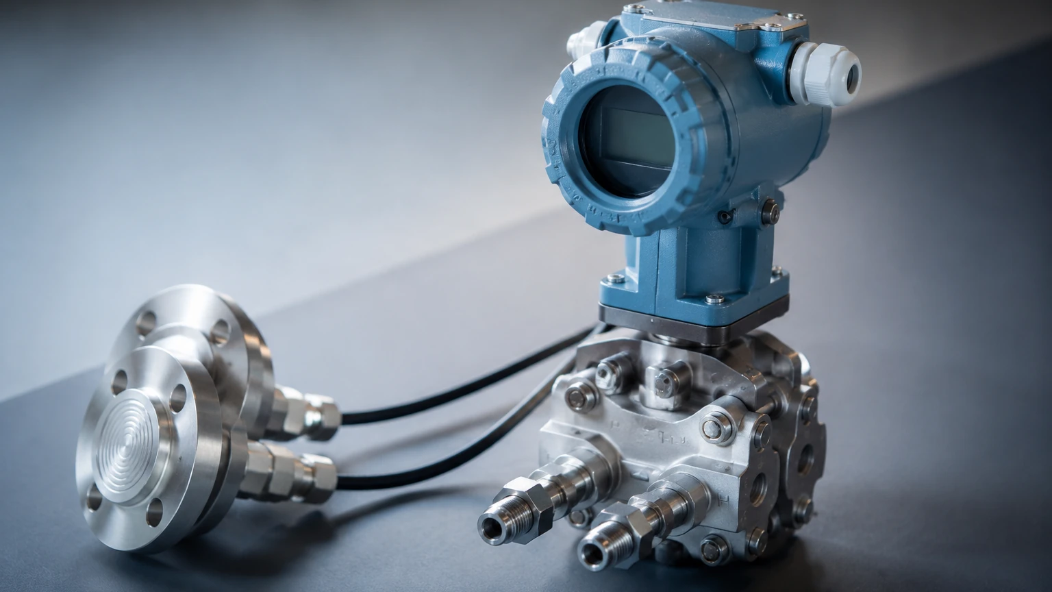
A modern pressure differential indicating transmitter consists of three primary functional blocks:
1. The Sensing Element: Usually a piezoresistive or capacitive sensor housed within a capsule. This element physically deforms under pressure, changing its electrical properties.
2. The Electronics Module: This converts the physical change from the sensor into a standardized electrical signal, typically 4-20mA DC, often with HART, PROFIBUS, or Foundation Fieldbus digital protocols.
3. The Indicator/Display: The "indicating" aspect of the transmitter refers to the local display (LCD or analog) that allows technicians to read the pressure or calculated level/flow directly at the point of measurement without needing to check the central control room.
Selection Criteria for Industrial Applications
Choosing a pressure differential indicating transmitter involves balancing accuracy requirements with the harshness of the process environment. The following table provides a reference for common selection factors:
| Criteria | Considerations | Typical Requirement |
| :— | :— | :— |
| Measurement Range | The maximum and minimum DP expected. | 0-1 kPa to 0-10 MPa (10 mbar to 100 bar) |
| Static Pressure | The maximum pressure the vessel or pipe is under. | Up to 40 MPa (400 bar) |
| Accuracy Class | The allowable margin of error. | 0.075%, 0.1%, or 0.5% of span |
| Wetted Materials | Chemical compatibility with the process fluid. | 316L Stainless Steel, Hastelloy C, Tantalum |
| Process Temperature | The heat of the fluid at the point of contact. | -40°C to +120°C (Direct), up to 400°C (with seals) |
| Output Protocol | Integration with the existing DCS/PLC. | 4-20mA HART, Modbus, or WirelessHART |
Remote Seals and Capillaries
In many B2B applications, the process fluid is corrosive, highly viscous, or prone to solidification. In these cases, a pressure differential indicating transmitter is equipped with remote diaphragm seals. These seals use a flexible membrane and a fill fluid (such as silicone oil) to transmit the pressure through a capillary tube to the transmitter body. This protects the sensitive electronics from the process medium.
Installation Considerations and Best Practices
The performance of a pressure differential indicating transmitter is heavily dependent on how it is installed. Improper mounting can lead to zero shifts, measurement lag, or total device failure.
Impulse Line Configuration
Impulse lines are the small-diameter pipes that carry the pressure from the process tap to the transmitter.
* Gas Measurement: The transmitter should be mounted above the process taps so that any condensed liquids can drain back into the process line.
* Liquid Measurement: The transmitter should be mounted below the process taps so that any trapped gas bubbles can rise back into the process line.
* Slope: Impulse lines should have a minimum slope of 1:12 (approx. 8%) to ensure proper drainage or venting.
Manifold Usage
A 3-valve or 5-valve manifold is essential for every pressure differential indicating transmitter. The manifold allows the operator to isolate the transmitter from the process for maintenance, vent trapped air, and, most importantly, equalize the pressure between the high and low sides to perform a zero-calibration check without removing the device from the line.
Environmental Protection
While most industrial transmitters are rated IP66 or IP67, extreme environments may require additional weather shields or heated enclosures to prevent the fill fluid in the capillaries from thickening in cold climates or the electronics from overheating in direct tropical sunlight.
Limitations and Common Risks
While highly versatile, the pressure differential indicating transmitter has specific limitations that engineers must account for during the design phase:
1. Density Sensitivity: Since DP level measurement relies on hydrostatic pressure, any change in the liquid's density (caused by temperature fluctuations or changes in chemical composition) will result in a measurement error. If density varies significantly, a radar or ultrasonic level sensor may be a better alternative. You can Review product options and application support to compare these technologies.
2. Clogging: In slurries or fluids with high solids content, the impulse lines or diaphragm faces can become clogged. Regular flushing or the use of extended diaphragm seals is required.
3. Static Pressure Effects: High static pressures can cause a "zero shift" in the transmitter. It is vital to perform a zero-adjustment at the operating static pressure rather than at atmospheric pressure.
Frequently Asked Questions (FAQs)
Q: How often should a pressure differential indicating transmitter be calibrated?
A: In stable environments, a biennial (every 2 years) calibration check is standard. However, in critical safety loops or high-vibration areas, annual or semi-annual checks are recommended.
Q: Can a DP transmitter measure the level of a boiling liquid?
A: Yes, but it requires a "wet leg" or a remote seal system. A dry impulse line would fill with condensate, creating an unpredictable head of liquid that would ruin the accuracy of the measurement.
Q: What is the difference between a pressure transmitter and a differential pressure transmitter?
A: A standard pressure transmitter has one process connection and measures pressure relative to the atmosphere (gauge) or a vacuum (absolute). A differential pressure transmitter has two connections (High and Low) and measures the difference between them.
Conclusion and Technical Support
The pressure differential indicating transmitter remains a workhorse of the process industry due to its proven reliability and the breadth of applications it can handle. From simple water tank level monitoring to complex flow calculations in chemical reactors, the DPIT provides the essential data needed for automated control.
When specifying an instrument for your project, always verify the chemical compatibility of the wetted parts and ensure the chosen range aligns with your process's normal operating window. For detailed specifications on various level measurement technologies, including radar and ultrasonic alternatives, visit the Main Page of our product catalog. Proper instrument selection is the first step toward a safe and optimized industrial process.
Download Pressure Differential Indicating Transmitter as a PDF