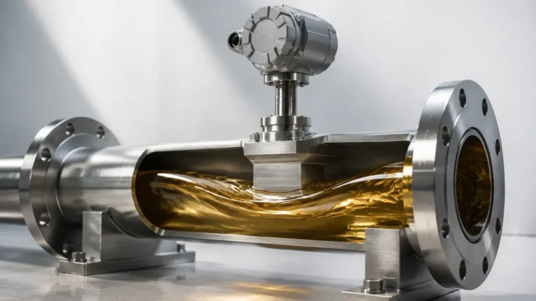
Resistance Temperature Detectors
Resistance Temperature Detectors
In industrial process control, the accuracy of level measurement is often inextricably linked to the precision of temperature data. Resistance temperature detectors (RTDs) serve as the backbone of thermal sensing in these environments, providing the stability and repeatability required for complex automation. Whether used as standalone sensors or integrated into sophisticated level measurement systems to compensate for density or dielectric fluctuations, understanding the mechanics and application of RTDs is essential for plant engineers and system integrators.
Measurement Principles of RTDs
The operation of resistance temperature detectors is based on a fundamental physical property of metals: electrical resistance changes in proportion to changes in temperature. This phenomenon is known as the piezoresistive effect or, more specifically in this context, the positive temperature coefficient (PTC).
The Resistance-Temperature Relationship
When a metal is heated, the thermal energy causes the atoms within the metallic lattice to vibrate more vigorously. These vibrations increase the frequency of collisions between the atoms and the flowing electrons (the electric current), thereby increasing the resistance to current flow. In most industrial RTDs, platinum is the preferred material because it exhibits a highly linear and stable relationship between temperature and resistance over a wide range.
The relationship is mathematically defined by the Callendar-Van Dusen equation for temperatures above 0°C:
\[ R_t = R_0 [1 + At + Bt^2] \]
Where:
* R_t is the resistance at temperature *t*.
* R_0 is the resistance at 0°C (typically 100 ohms for a Pt100 sensor).
* A and B are constants derived from the properties of the metal.
For industrial applications, the most common standard is the DIN/IEC 60751, which defines the "Alpha" (α) coefficient—the average change in resistance per ohm per degree Celsius between 0°C and 100°C. The standard value for platinum is 0.00385 Ω/Ω/°C.
Sensing Elements: Pt100 vs. Pt1000
The most frequent designations encountered in the field are Pt100 and Pt1000.
* Pt100: This sensor has a resistance of 100 ohms at 0°C. It is the industry standard, offering a balance between signal strength and sensitivity to lead wire resistance.
* Pt1000: This sensor has a resistance of 1,000 ohms at 0°C. Because its base resistance is higher, the relative impact of lead wire resistance is significantly reduced, making it ideal for 2-wire configurations or battery-powered applications where low current consumption is required.
Types and Construction of Resistance Temperature Detectors
RTD elements are generally manufactured in two primary formats, each suited to specific environmental conditions and precision requirements.
Thin-Film Elements
Thin-film RTDs are produced by depositing a microscopic layer of platinum onto a ceramic substrate using vacuum evaporation or sputtering. The layer is then etched using lithography to create the resistive circuit. These elements are compact, highly resistant to vibration, and cost-effective. They are the preferred choice for most standard industrial level and temperature transmitters where high-G forces or mechanical shocks are present.
Wire-Wound Elements
Wire-wound RTDs consist of a fine platinum wire coiled around a ceramic or glass mandrel. These are often housed inside a protective tube filled with insulating powder. While more fragile and expensive than thin-film versions, wire-wound sensors offer superior accuracy and stability over extremely wide temperature ranges. They are typically reserved for laboratory standards or critical process points requiring the highest possible precision.
The Role of RTDs in Level Measurement
While RTDs are primary temperature sensors, their role in level measurement is critical for maintaining system integrity and accuracy. For more information on how these sensors integrate with broader measurement arrays, you can Review product options and application support on the Welk Main Page.
1. Density Compensation in Hydrostatic Level
Hydrostatic level transmitters measure the pressure exerted by a liquid column. However, the density of a liquid changes with temperature. Without an RTD to provide real-time temperature data, a hydrostatic sensor cannot distinguish between a change in liquid level and a change in liquid density, leading to significant measurement errors.
2. Speed of Sound Correction in Ultrasonic Sensors
Ultrasonic level sensors calculate distance based on the time it takes for a sound wave to travel to the surface and back. The speed of sound in air (or other gases) changes by approximately 0.6 meters per second for every degree Celsius. Integrated resistance temperature detectors allow the transmitter to adjust the time-of-flight calculation in real-time.
3. Dielectric Constant Stability in Radar
In guided wave radar (GWR) applications, the dielectric constant of the vapor space above the liquid can be affected by temperature and pressure. High-precision RTDs provide the necessary data to compensate for these shifts, ensuring the radar pulse velocity is correctly interpreted.
Selection Criteria and Accuracy Classes
When selecting resistance temperature detectors, engineers must match the sensor's tolerance class to the process requirements. The IEC 60751 standard defines these classes based on the allowable deviation at a given temperature.
| Tolerance Class | Accuracy at 0°C | Accuracy at 200°C | Recommended Application |
| :— | :— | :— | :— |
| Class AA (1/3 DIN) | ±0.10°C | ±0.27°C | Laboratory and high-precision custody transfer |
| Class A | ±0.15°C | ±0.35°C | General industrial process control |
| Class B | ±0.30°C | ±0.80°C | Non-critical monitoring and HVAC |
| Class C | ±0.60°C | ±1.60°C | Basic indication where precision is not vital |
Wiring Configurations
The method used to connect the RTD to the control system significantly impacts accuracy due to lead wire resistance.
* 2-Wire: The lead wire resistance is added directly to the sensor resistance, creating a positive offset error. This is only suitable for Pt1000 sensors with very short cable runs.
* 3-Wire: The most common industrial configuration. It uses a third wire to measure the lead resistance and subtract it from the total, assuming all wires have identical resistance.
* 4-Wire: The most accurate method. It uses two wires to carry the excitation current and two independent wires to measure the voltage drop across the RTD element, completely eliminating the effect of lead wire resistance.
Installation Considerations
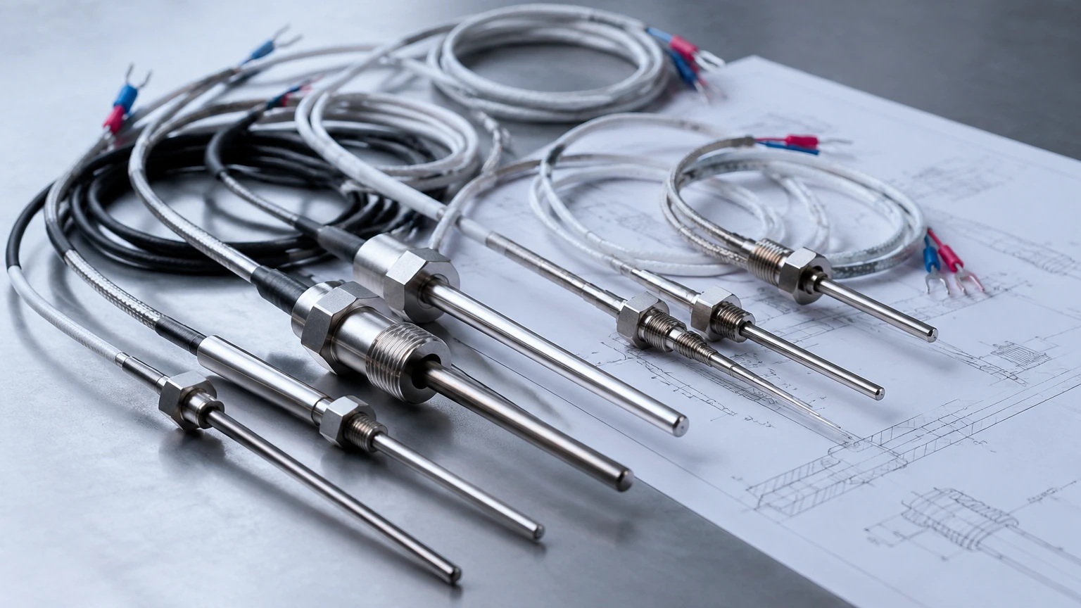
Proper installation is paramount to ensuring the longevity and accuracy of resistance temperature detectors.
1. Immersion Depth: To avoid conduction errors (where heat escapes through the sensor housing), the RTD should be immersed to a depth at least 10 times the diameter of the protection tube (thermowell).
2. Thermowell Selection: In high-velocity flows or high-pressure tanks, RTDs must be installed inside thermowells. This protects the sensor from mechanical damage and allows for replacement without depressurizing the vessel.
3. Thermal Paste: For faster response times, a thermal conductive paste can be used between the RTD element and the inner wall of the thermowell to reduce thermal lag.
4. Environmental Sealing: In chemical or oil and gas applications, the connection head must be appropriately rated (e.g., IP67 or NEMA 4X) and may require explosion-proof (Ex d) or intrinsically safe (Ex i) certifications.
Limitations and Potential Risks
While highly reliable, RTDs are not suitable for every application. Engineers should be aware of the following limitations:
* Self-Heating: To measure resistance, a small current must be passed through the sensor. This current generates heat ($I^2R$). If the excitation current is too high, the sensor will report a temperature higher than the actual process temperature. Most modern transmitters limit this current to less than 1 mA.
* Response Time: Compared to thermocouples, RTDs have a slower response time due to their larger thermal mass and the need for protective sheathing.
* Vibration: While thin-film RTDs are robust, extreme vibration can lead to mechanical failure of the lead wire connections or the ceramic substrate.
* Temperature Ceiling: RTDs are generally limited to temperatures below 600°C or 850°C (depending on construction), whereas thermocouples can measure much higher ranges.
Comparison: RTDs vs. Thermocouples
| Feature | RTD (Platinum) | Thermocouple |
| :— | :— | :— |
| Accuracy | High | Medium to Low |
| Stability | Excellent (Long-term) | Prone to drift |
| Linearity | Excellent | Fair |
| Temperature Range | -200°C to +850°C | -270°C to +2300°C |
| Response Time | Slower | Faster |
| Cost | Higher | Lower |
Frequently Asked Questions (FAQ)
Q: How often should resistance temperature detectors be calibrated?
A: In standard industrial applications, annual calibration is recommended. However, in critical processes or high-vibration environments, semi-annual checks may be necessary to account for potential drift or mechanical fatigue.
Q: Can I use a 3-wire RTD with a 2-wire transmitter?
A: Yes, by jumping two of the leads at the transmitter terminals, but you will lose the lead-wire compensation benefits, effectively turning it into a 2-wire system with the associated accuracy losses.
Q: What causes an RTD to fail?
A: The most common causes are moisture ingress into the sensor housing (causing insulation resistance breakdown), mechanical breakage due to vibration, and contamination of the platinum element by metal vapors at very high temperatures.
Q: Why is my RTD reading fluctuating rapidly?
A: This is often caused by electromagnetic interference (EMI). Ensure that shielded cables are used and that the shield is grounded at only one end (typically at the control system) to prevent ground loops.
By carefully selecting the appropriate tolerance class, wiring configuration, and mounting method, resistance temperature detectors provide the reliable data necessary for both primary temperature monitoring and secondary compensation in level measurement systems. Their stability makes them an indispensable tool in the pursuit of process optimization and safety.