Sample Serve
Sample Serve
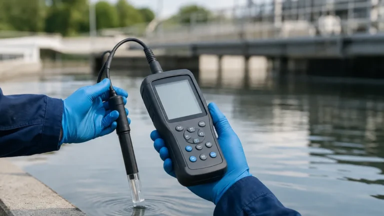
In the landscape of industrial automation and environmental monitoring, the concept of a "sample serve" workflow—the systematic collection, management, and reporting of fluid samples—relies heavily on the precision of level measurement instrumentation. Whether managing groundwater monitoring wells, industrial wastewater discharge, or chemical processing tanks, the ability to serve accurate samples is predicated on knowing the exact volume, head pressure, and surface level of the medium in question.
For engineers and project managers, selecting the right level measurement technology is not merely a matter of hardware acquisition; it is about ensuring the integrity of the data that drives the entire sampling lifecycle. This article explores the technical principles of level measurement, how these technologies support sampling operations, and the critical selection criteria for industrial applications.
The Role of Level Measurement in Sampling Workflows
Level measurement serves as the foundational data point for most sampling protocols. In environmental and industrial contexts, "sample serve" refers to the process where a sample is collected based on specific triggers—often time-weighted or flow-proportional.
1. Volume Calculation: Accurate level data allows for the conversion of linear height into volume, ensuring that the sample collected is representative of the total batch.
2. Pump Control: In automated sampling systems, level sensors prevent dry-running of pumps and ensure that intake tubes are submerged at the correct depth.
3. Flow Proportionality: In open channels, level sensors (typically ultrasonic or radar) measure the head height over a flume or weir to calculate flow rates, which then dictates the frequency of sample collection.
Reliable instrumentation from professional manufacturers like Welk ensures that these processes are automated with high precision, reducing human error and improving the audit trail for regulatory compliance.
Core Measurement Technologies and Principles
To implement an effective sampling strategy, one must understand the physics behind the measurement. Different media and environments require specific sensing technologies.
Radar Level Measurement
Radar level meters utilize Frequency Modulated Continuous Wave (FMCW) or pulse radar technology. The sensor emits a high-frequency signal (typically 26GHz or 80GHz) that travels to the product surface and reflects back.
* Principle: The time-of-flight or frequency shift is measured to determine the distance.
* Advantages: Radar is non-contact and unaffected by changes in temperature, pressure, or the presence of vapors and dust. This makes it ideal for volatile chemical sampling where the integrity of the headspace must be maintained.
* Application: High-precision tanks and corrosive environments.
Ultrasonic Level Sensors
Ultrasonic sensors emit high-frequency sound waves that bounce off the liquid surface.
* Principle: The sensor measures the time interval between the emission of the ultrasonic pulse and the reception of the echo. Since the speed of sound is known, the distance can be calculated.
* Advantages: Cost-effective and easy to install for water-based applications.
* Limitations: Because sound requires a medium (air), its speed is affected by temperature fluctuations. Most modern sensors, such as those found on the Welk Main Page, include integrated temperature compensation to mitigate this.
Hydrostatic Level Transmitters
Hydrostatic sensors are contact-based and measure the pressure exerted by a liquid column.
* Principle: Based on Stevin’s law ($P = \rho gh$), the pressure at the bottom of a tank is directly proportional to the height of the liquid ($h$), the density ($\rho$), and gravity ($g$).
* Advantages: Excellent for deep wells and vented tanks where non-contact sensors might struggle with narrow geometries.
* Application: Groundwater monitoring and deep-sump wastewater sampling.
Magnetic Level Gauges
Magnetic level gauges provide both local visual indication and remote signal transmission.
* Principle: A float containing a permanent magnet moves with the liquid level, actuating magnetic flaps or a continuous transmitter outside the chamber.
* Advantages: Highly reliable for high-pressure boilers or tanks where electronic failure cannot be tolerated.
Selection Criteria for Sampling Applications
Choosing the wrong instrument can lead to "sample serve" failures, such as missed samples or inaccurate volume reports. The following table provides a comparison for selection based on common industrial variables.
| Feature | Radar (80GHz) | Ultrasonic | Hydrostatic | Magnetic Gauge |
| :— | :— | :— | :— | :— |
| Accuracy | ±1 mm (0.04 in) | ±0.25% of range | ±0.1% to 0.5% | ±5 mm (0.2 in) |
| Medium | Liquids/Solids | Liquids | Liquids only | Liquids only |
| Contact | Non-contact | Non-contact | Contact | Contact |
| Max Temp | +250°C (482°F) | +80°C (176°F) | +125°C (257°F) | +400°C (752°F) |
| Max Pressure | 4.0 MPa | Ambient | 20 MPa | 16 MPa |
| Foam Impact | Low to Moderate | High | None | None |
Key Evaluation Questions
Before finalizing a specification, engineers should confirm:
1. What is the dielectric constant of the medium? (Crucial for radar).
2. Is there heavy foam or turbulence? (May require hydrostatic or guided wave radar).
3. What are the mounting constraints? (Nozzle size and height).
Installation and Calibration Guidelines
For a level meter to support a reliable sampling workflow, installation must follow strict engineering standards. Even the most advanced 80GHz radar will fail if poorly positioned.
1. Avoiding the "Dead Zone"
Every sensor has a "dead zone" or "blocking distance" near the face of the transducer where measurement is impossible. For ultrasonic sensors, this is typically 0.2 m to 0.5 m (8 to 20 inches). Ensure the maximum liquid level never enters this zone to prevent signal loss during peak filling.
2. Beam Angle and Obstructions
Radar and ultrasonic signals spread in a cone. If the beam hits a ladder, agitator, or the tank wall, it creates a false echo.
* Tip: Install the sensor at least 200 mm (8 inches) away from the tank wall for every 1 meter of depth, or use a narrow-beam 80GHz radar to bypass internal obstructions.
3. Stilling Wells
In applications with heavy surface turbulence or foam (common in chemical mixing), a stilling well—a vertical pipe that acts as a bypass—can provide a calm surface for the sensor to measure, ensuring the "sample serve" data remains stable.
4. Calibration
Calibration should be performed against a physical measurement (dip tape). Most digital transmitters allow for a two-point calibration:
* 4mA (Empty): The distance from the sensor to the bottom of the tank.
* 20mA (Full): The distance from the sensor to the maximum fill line.

Overcoming Common Challenges in Fluid Sampling
Foam and Vapor Interference
In wastewater treatment, foam is a frequent byproduct. Ultrasonic waves are often absorbed by foam, leading to "lost echo" errors. In these instances, radar is preferred as it can penetrate light foam, or hydrostatic transmitters can be used as they are entirely unaffected by surface conditions.
Temperature Gradients
In outdoor sampling sites, solar heating of the tank headspace can create temperature gradients. This changes the speed of sound, causing ultrasonic sensors to report errors of up to 5% if not properly compensated. Using a remote temperature probe or switching to radar (which is unaffected by air temperature) resolves this issue.
Build-up and Maintenance
Sampling of slurries or viscous fluids can lead to material build-up on contact-based sensors. Hydrostatic diaphragms can become coated, leading to "drift." Non-contact radar with a PTFE-faced antenna is the standard solution for minimizing maintenance in these "dirty" applications.
Frequently Asked Questions (FAQs)
Q: How often should level meters be calibrated for regulatory sampling?
A: For most industrial discharge permits, an annual calibration check is required. However, for high-criticality "sample serve" operations, a quarterly verification against a manual gauge is recommended.
Q: Can one sensor handle both level measurement and flow calculation?
A: Yes. Many modern ultrasonic and radar transmitters have built-in libraries for standard flumes (Parshall, Palmer-Bowlus) and weirs. They can output both the level and the instantaneous flow rate via 4-20mA or Modbus protocols.
Q: What is the benefit of 80GHz radar over 26GHz for sampling tanks?
A: 80GHz radar has a much narrower beam angle (around 3 degrees) and a shorter wavelength. This allows it to measure through small nozzles and provides better signal separation from foam or condensate, leading to higher reliability in complex tank geometries.
Q: How do I integrate these sensors into my existing sampling software?
A: Most professional level meters support standard industrial protocols. For remote or environmental sampling, look for sensors with low-power 4-20mA outputs or SDI-12 interfaces that can be powered by battery-operated data loggers.
Conclusion
Effective "sample serve" operations are built on the accuracy of the underlying level data. By understanding the measurement principles of radar, ultrasonic, and hydrostatic technologies, and by following rigorous installation practices, industrial operators can ensure that their sampling programs are both compliant and representative. For detailed technical specifications and product selection support, engineers are encouraged to review the comprehensive resources available on the Main Page of the Welk instrumentation portal. Accurate measurement is the first step toward reliable process control and environmental stewardship.