Dissolved O2 Sensor
Dissolved O2 Sensor
In industrial process control and environmental monitoring, the measurement of dissolved oxygen (DO) is a critical parameter for ensuring product quality, process efficiency, and regulatory compliance. A dissolved o2 sensor is an analytical instrument used to determine the amount of gaseous oxygen (O2) dissolved in a liquid unit, typically expressed in milligrams per liter (mg/L), parts per million (ppm), or percentage of saturation. While level measurement technologies—such as those found on the Main Page—manage the volume and containment of liquids, dissolved oxygen sensors monitor the chemical health and reactivity of the medium within those containers.
This guide provides a comprehensive technical overview of dissolved o2 sensor technologies, their operating principles, selection criteria, and practical installation considerations for engineering professionals.
Measurement Principles of Dissolved O2 Sensors
Understanding how a dissolved o2 sensor functions is essential for selecting the right technology for a specific application. There are two primary categories of sensing technology used in modern industrial environments: electrochemical and optical.
1. Electrochemical Sensors
Electrochemical sensors operate by reducing oxygen at a cathode, which generates an electrical current proportional to the oxygen partial pressure. These are further divided into two types:
* Galvanic Sensors: These sensors consist of two dissimilar metals (typically a silver cathode and a lead or zinc anode) immersed in an electrolytic solution. When oxygen permeates the sensor membrane, a spontaneous redox reaction occurs. Because the reaction is spontaneous, these sensors require no "warm-up" time and generate their own small voltage.
* Polarographic Sensors: Also known as Clark electrodes, these sensors utilize a gold or platinum cathode and a silver anode. Unlike galvanic sensors, they require an external polarizing voltage to drive the oxygen reduction. They typically require a warm-up period of 15 to 60 minutes to stabilize the polarization before accurate readings can be taken.
Both electrochemical types rely on a gas-permeable membrane. The rate of oxygen diffusion through the membrane is temperature-dependent, necessitating integrated temperature compensation.
2. Optical Sensors (Luminescence-Based)
Optical dissolved o2 sensors utilize the principle of "fluorescence quenching." The sensor tip contains a sensing element coated with a luminescent dye (luminophore). An LED inside the sensor emits blue light, exciting the luminophore, which then emits red light as it returns to its ground state. If oxygen molecules are present, they collide with the excited luminophore and "quench" the luminescence.
The sensor measures either the intensity or the lifetime (decay time) of the red light. The more oxygen present, the shorter the lifetime of the luminescence. This technology is increasingly preferred in industrial automation due to its stability and low maintenance requirements.
Comparison of Sensor Technologies
Choosing between electrochemical and optical sensors involves balancing performance requirements against operational constraints. The following table outlines the key differences:
| Feature | Electrochemical (Galvanic/Polarographic) | Optical (Luminescent) |
| :— | :— | :— |
| Measurement Principle | Chemical reduction of O2 | Fluorescence quenching |
| Oxygen Consumption | Consumes oxygen during measurement | Does not consume oxygen |
| Flow Requirement | Requires constant flow (0.3 m/s min) | No flow requirement |
| Warm-up Time | 0 to 60 minutes | Instantaneous |
| Maintenance | High (Membrane/Electrolyte replacement) | Low (Periodic cap replacement) |
| Calibration Frequency | Frequent (Weekly/Monthly) | Infrequent (Bi-annually/Annually) |
| Sensitivity to H2S | High (Can poison the electrode) | Low/None |
| Initial Cost | Lower | Higher |
| Long-term Cost | Higher (Labor and consumables) | Lower |
Selection Criteria for Industrial Applications
When specifying a dissolved o2 sensor for water treatment, chemical processing, or oil and gas applications, engineers must evaluate several environmental and process factors.
Process Medium and Contaminants
The chemical composition of the liquid is the first consideration. In wastewater treatment, for example, the presence of hydrogen sulfide (H2S) can permeate the membranes of electrochemical sensors and poison the anode, leading to rapid sensor failure. In such environments, optical sensors are the superior choice. Conversely, in ultra-pure water applications (like boiler feed water), high-sensitivity polarographic sensors may offer better resolution at parts-per-billion (ppb) levels.
Temperature and Pressure
Dissolved oxygen solubility is heavily influenced by temperature and atmospheric pressure. Most industrial sensors are rated for temperatures between 0°C and 50°C, though specialized high-temperature versions exist for fermentation or sterilization processes (up to 130°C). Pressure ratings typically range from atmospheric to 10 bar (145 psi). It is vital to ensure the sensor housing and membrane can withstand the process pressure without deformation.
Flow Conditions
Because electrochemical sensors consume oxygen to produce a signal, they require a continuous flow of liquid across the membrane to prevent the depletion of oxygen at the sensor interface. If the liquid is stagnant, the reading will artificially drop. If the application involves low-flow or static tanks, an optical dissolved o2 sensor should be used, as it does not consume oxygen and provides accurate readings regardless of flow velocity.
Installation and Positioning Considerations
Proper installation is as critical as sensor selection. A poorly placed sensor will provide unrepresentative data, leading to inefficient process control (such as over-aeration in wastewater basins, which wastes significant energy).
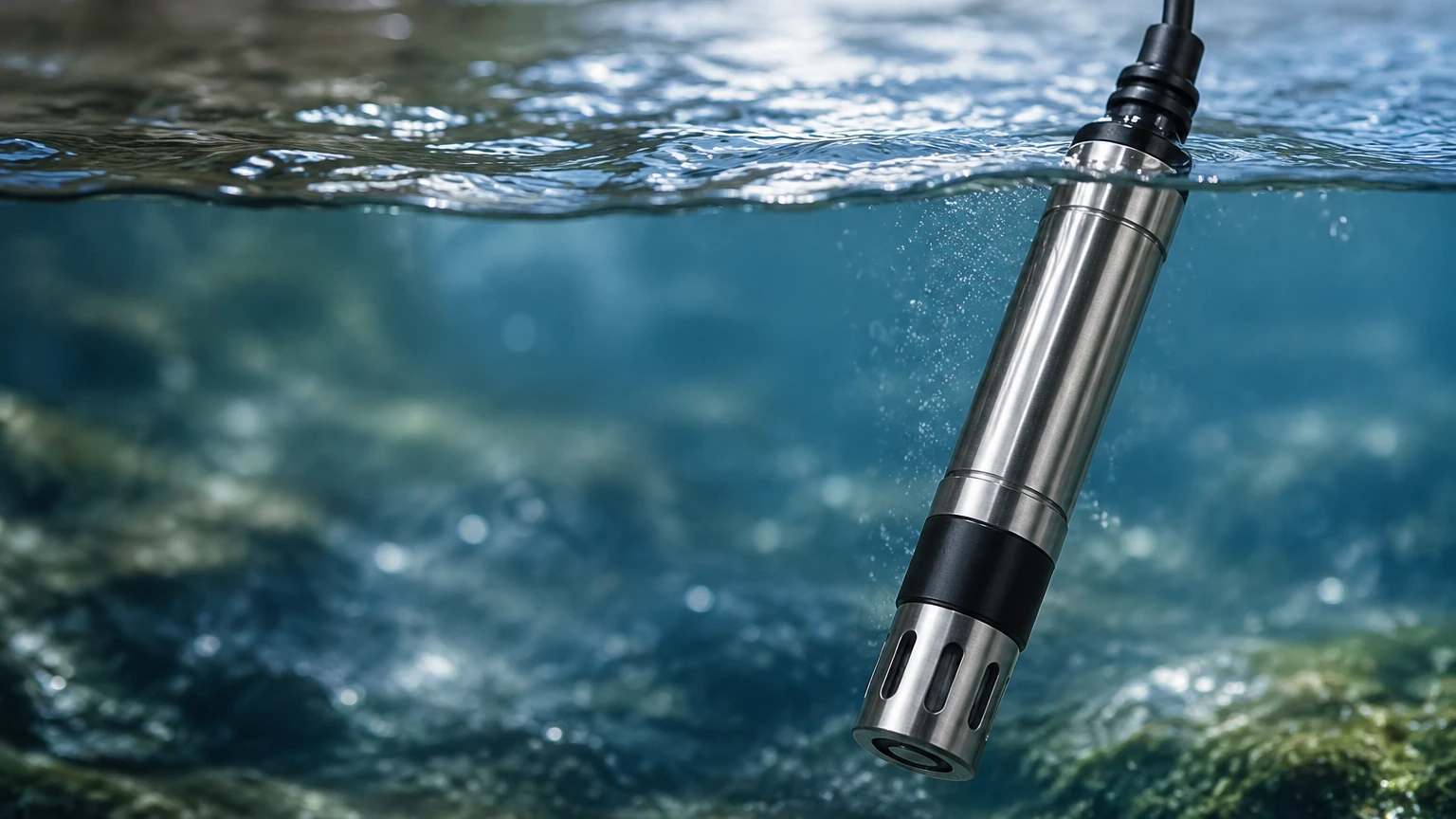
1. Orientation: Sensors should generally be installed at an angle (typically 15° to 45° from the vertical) to prevent air bubbles from becoming trapped on the sensing surface. Trapped bubbles will cause the sensor to read the oxygen concentration of the air bubble rather than the liquid, leading to falsely high readings.
2. Submersion Depth: The sensor must be submerged deep enough to avoid the influence of surface aeration but not so deep that it rests in the sludge or sediment layer at the bottom of a tank. In large basins, the sensor is often mounted on a floating ballasted assembly or a telescopic boom.
3. Integration with Level Meters: In many industrial tanks, DO monitoring is paired with level measurement. For instance, in an aeration tank, a hydrostatic level transmitter or an ultrasonic level sensor (details available on the Main Page) ensures the basin maintains the correct volume, while the DO sensor controls the blowers. Ensuring that the DO sensor is positioned within the active mixing zone identified by the tank's level and geometry is essential for representative sampling.
4. Accessibility: Sensors require periodic cleaning and calibration. Installation points should be easily accessible by technicians without requiring confined space entry or specialized climbing gear.
Maintenance and Calibration
To maintain accuracy, a dissolved o2 sensor requires a structured maintenance program.
Cleaning
Biofouling is the most common cause of sensor drift. In wastewater applications, algae, bacteria, and fats can coat the membrane or optical cap. Automated cleaning systems, such as compressed air blasts or water jets integrated into the sensor mounting, can significantly extend the interval between manual cleanings.
Calibration Methods
There are two standard methods for calibrating a dissolved o2 sensor:
* Air-Saturated Water: The sensor is placed in a container of water that has been bubbled with air until it is fully saturated. This is highly accurate but time-consuming.
* Water-Saturated Air: The sensor is held in the air just above a water surface in a closed container. Since the partial pressure of oxygen in water-saturated air is the same as in air-saturated water, this provides a reliable 100% saturation point and is much easier to perform in the field.
Limitations and Common Risks
While robust, dissolved o2 sensors have specific limitations that can lead to measurement errors:
* Membrane Fragility: In electrochemical sensors, the thin Teflon or silicone membrane is susceptible to punctures from sharp debris in the process flow.
* Salinity Effects: Oxygen solubility decreases as salinity increases. If the process involves varying salt concentrations (e.g., estuarine water or brine processing), the transmitter must be programmed with a salinity correction factor to maintain accuracy.
* Photo-bleaching: In optical sensors, excessive exposure to direct sunlight or high-intensity internal LED pulses can eventually degrade the luminophore dye, requiring the replacement of the sensor cap.
Frequently Asked Questions
Q: How often should I calibrate my optical dissolved o2 sensor?
A: While optical sensors are very stable, it is recommended to check the calibration every 3 to 6 months. In stable, clean-water applications, some users find that annual calibration is sufficient.
Q: Can a dissolved o2 sensor be used in oil-based liquids?
A: Generally, no. Standard DO sensors are designed for aqueous solutions. Oil can coat the membrane or optical window, blocking oxygen diffusion or light transmission and causing sensor failure.
Q: What is the difference between % Saturation and mg/L?
A: % Saturation measures the oxygen partial pressure relative to the maximum amount of oxygen the water can hold at that specific temperature and pressure. mg/L (or ppm) is the actual mass of oxygen dissolved in the water. Most modern transmitters can toggle between these units.
Q: Does the sensor require a specific controller?
A: Most industrial dissolved o2 sensors output a 4-20mA signal, RS485 (Modbus), or a proprietary digital signal that requires a compatible transmitter or controller to interpret the data and provide a display and relay outputs.
By carefully evaluating the technology type, process conditions, and installation requirements, engineering teams can implement a dissolved o2 sensor solution that provides reliable data for years of operation. For more information on integrating these sensors with broader industrial instrumentation and level control systems, refer to the technical resources on the Main Page.