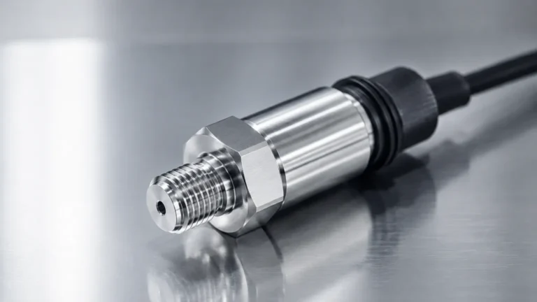
Fmr53
Fmr53
In the landscape of industrial automation and process control, non-contact level measurement has become the gold standard for reliability and low maintenance. Among the various technologies available, the FMR53 stands as a significant representative of high-frequency radar level measurement. Specifically designed for liquid applications, this 26 GHz pulse radar sensor addresses the needs of industries ranging from water treatment to chemical processing. Understanding the technical nuances, measurement principles, and installation requirements of the FMR53 is essential for engineers tasked with optimizing vessel management and ensuring process safety.
As a professional manufacturer of industrial level measurement instruments, Welk provides advanced technology and reliable solutions for global customers. For those seeking comprehensive product options and technical support for radar level meters, visiting the Main Page offers a gateway to specialized engineering resources and cost-effective instrumentation.
The Principle of Radar Level Measurement
To appreciate the capabilities of the FMR53, one must first understand the fundamental physics of radar level sensing. The device operates on the Time-of-Flight (ToF) principle, specifically utilizing microwave pulses.
Pulse Radar Technology
The radar sensor emits high-frequency microwave pulses—typically in the 26 GHz K-band range—from its antenna. These pulses travel at the speed of light toward the surface of the medium being measured. When the pulses encounter a change in the dielectric constant ($ε_r$) at the interface between the air (or gas phase) and the liquid surface, a portion of the energy is reflected back toward the sensor.
The onboard electronics measure the time elapsed between the emission of the pulse and the reception of the echo. Since the speed of the microwave signal is constant, the distance ($D$) from the sensor reference point to the liquid surface can be calculated using the formula:
$$D = \frac{c \times t}{2}$$
Where:
- c is the speed of light.
- t is the measured time-of-flight.
The level ($L$) is then determined by subtracting the distance ($D$) from the total tank height ($H$):
$$L = H – D$$
The Importance of the Dielectric Constant
The accuracy and reliability of the FMR53 are heavily dependent on the dielectric constant of the medium. Materials with high dielectric constants, such as water ($ε_r ≈ 80$), reflect radar signals very efficiently. Conversely, hydrocarbons and oils often have low dielectric constants ($ε_r < 2.0$), which result in weaker signal reflections. The FMR53 is engineered with sensitive signal processing algorithms to detect these faint echoes, but users must confirm the $ε_r$ of their medium during the selection process to ensure the signal-to-noise ratio remains within acceptable limits.
Technical Specifications and Evaluation Criteria
When evaluating the FMR53 for a specific application, several technical parameters must be scrutinized. This model is generally positioned for basic to moderate process conditions, offering a balance between performance and cost.
Key Performance Indicators
1. Frequency: 26 GHz. This high frequency allows for smaller antenna sizes and narrower beam angles compared to older 6 GHz technology, making it easier to install in small tanks or vessels with internal obstructions.
2. Measuring Range: Typically up to 20 meters (approximately 66 feet) for liquid applications, depending on the antenna configuration and the reflectivity of the medium.
3. Accuracy: Standard accuracy is often within ±3 mm, providing the precision required for inventory control and process monitoring.
4. Process Temperature: Designed to operate in environments ranging from -40°C to +150°C (-40°F to +302°F).
5. Process Pressure: Capable of withstanding pressures from vacuum up to 40 bar (580 psi), depending on the flange and seal materials.
Selection Table: FMR53 Configuration Options
| Feature | Standard Option | Extended/Custom Option |
| :— | :— | :— |
| Antenna Type | Horn (40mm/1.5") | Rod (PTFE clad) |
| Housing Material | Aluminum PBT | Stainless Steel (316L) |
| Output Signal | 4-20mA HART | PROFIBUS PA / FOUNDATION Fieldbus |
| Process Connection | Threaded (G1.5, NPT1.5) | Flanged (DN50 – DN150) |
| Certifications | ATEX, IECEx, FM, CSA | SIL2 / SIL3 (Functional Safety) |
Application Engineering and Practical Selection
Choosing the right radar level meter involves more than just matching pressure and temperature ratings. Engineers must consider the geometry of the vessel and the physical properties of the liquid.
When to Choose FMR53
The FMR53 is particularly well-suited for:
- Small Vessels: Due to its 26 GHz frequency, the signal beam is relatively narrow, reducing the risk of interference from tank walls.
- Corrosive Media: When equipped with a PTFE-clad rod antenna, the sensor provides excellent resistance to aggressive chemicals.
- Storage Tanks: It is an ideal solution for monitoring water, solvents, and chemicals in atmospheric storage tanks.
Limitations to Consider
While versatile, the FMR53 has limitations that may necessitate a different model or technology:
- Heavy Foam: Thick, dense foam can absorb radar signals, leading to signal loss. In such cases, guided wave radar (GWR) or hydrostatic transmitters might be more appropriate.
- Extremely Turbulent Surfaces: While software filters can mitigate some turbulence, extreme agitation may require a stilling well to provide a stable surface for measurement.
- Very Low Dielectric Media: For liquefied gases or very pure hydrocarbons with $ε_r < 1.4$, high-sensitivity FMCW radar or GWR is often preferred.
Installation Guidelines for Optimal Performance
The performance of a radar level meter is only as good as its installation. Improper mounting is the most common cause of measurement errors in the field.
Nozzle Considerations
The nozzle height and diameter play a critical role in signal integrity. Ideally, the antenna should extend below the nozzle to prevent the microwave pulses from reflecting off the nozzle walls. If the nozzle is long, internal reflections (ringing) can create a "blind zone" at the top of the tank where measurement is impossible.
Beam Angle and Obstructions
Every radar sensor has a beam angle, which defines the cone-shaped area where the signal travels. For the FMR53, the beam angle typically ranges from 8° to 20° depending on the antenna size.
- Clearance: The beam must remain clear of internal obstructions such as agitators, heating coils, ladders, and support beams.
- Mapping: If obstructions cannot be avoided, most modern radar meters allow for "false echo mapping." This process involves recording the echoes from static internal structures and instructing the software to ignore them.
Mounting Position
- Avoid the Center: Do not mount the sensor in the exact center of a domed tank, as this can cause multiple reflections that interfere with the primary signal.
- Distance from Wall: The sensor should be mounted at least 200 mm (8 inches) away from the tank wall to avoid interference from the wall surface.
- Inlet Interference: Ensure the sensor is not positioned directly above the liquid inlet, as the falling stream will cause erratic readings.

Maintenance and Troubleshooting
One of the primary advantages of non-contact radar like the FMR53 is the lack of moving parts, which significantly reduces maintenance requirements. However, periodic checks are still necessary.
Common Issues and Solutions
1. Condensation and Buildup: In applications with high humidity or vapor, condensation can form on the antenna. While 26 GHz radar is somewhat resistant to this, heavy buildup can attenuate the signal. PTFE-coated antennas or air purging systems can help mitigate this.
2. Signal Loss (E104/E106 Errors): This usually indicates that the reflected signal is too weak. Check if the medium's dielectric constant has changed or if there is excessive foam or turbulence.
3. Drift: Radar measurement is generally immune to drift, but if the reference point (mounting flange) shifts due to vessel expansion or mechanical stress, the zero point may need recalibration.
Frequently Asked Questions (FAQ)
Q: Can the FMR53 be used for solids measurement?
A: No, the FMR53 is optimized for liquids. For bulk solids, a radar with a larger horn antenna and specialized dust-handling capabilities, such as an 80 GHz model or a dedicated solids radar, is recommended.
Q: How does temperature affect the measurement?
A: Unlike ultrasonic sensors, radar signals are not affected by air temperature or gas composition. However, the electronics and seals of the FMR53 must remain within their rated temperature limits to prevent hardware failure.
Q: Is a stilling well necessary?
A: A stilling well is not required for standard applications but is highly recommended for vessels with heavy surface foam, high turbulence, or very low dielectric liquids. It focuses the radar energy and provides a calm surface for measurement.
Q: What is the "Blocking Distance"?
A: The blocking distance (or dead zone) is the area immediately below the sensor where measurement is not possible. For the FMR53, this is typically around 200 mm to 400 mm depending on the antenna and nozzle configuration.
Conclusion
The FMR53 represents a robust and versatile solution for industrial liquid level measurement. By leveraging 26 GHz pulse radar technology, it provides high accuracy and ease of installation in a variety of process environments. However, successful implementation requires a thorough understanding of the medium's dielectric properties, vessel geometry, and proper installation techniques.
For engineers looking to implement reliable level sensing technology, it is vital to partner with manufacturers who offer not only high-quality hardware but also the technical expertise to guide the selection process. To explore a wide range of radar, ultrasonic, and hydrostatic level solutions, visit the Main Page for professional guidance and product specifications tailored to your industrial automation needs.