Tank Level Sensing
Tank Level Sensing
Tank level sensing is a critical component in modern industrial automation, ensuring the safety, efficiency, and accuracy of processes across sectors such as water treatment, chemical processing, and oil and gas production. Selecting the appropriate sensing technology requires a deep understanding of the physical principles governing each method, as well as the specific environmental conditions of the application. This guide provides a technical overview of common tank level sensing technologies, their selection criteria, and practical installation considerations for engineering professionals.
Principles of Industrial Tank Level Sensing
Before selecting a specific instrument, it is essential to understand how different technologies interact with the stored media and the vessel environment. Sensing methods are generally categorized into non-contact and contact technologies.
Radar Level Measurement
Radar level meters utilize electromagnetic waves to determine the distance to the product surface. There are two primary types: Frequency Modulated Continuous Wave (FMCW) and Guided Wave Radar (GWR).
* FMCW Radar (Non-contact): The sensor emits a high-frequency signal that increases in frequency over time. The signal reflects off the surface of the medium and is received by the antenna. The difference between the emitted and received frequency is proportional to the distance. Because radar waves are electromagnetic, they are not affected by vacuum, high pressure, or temperature fluctuations.
* Guided Wave Radar (GWR): This contact-based method uses a probe (rod or cable) to guide low-power microwave pulses. When the pulse hits the media, the change in dielectric constant causes a reflection. GWR is particularly effective in tanks with internal obstructions or low-dielectric fluids.
Ultrasonic Level Sensing
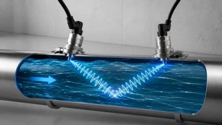
Ultrasonic sensors operate on the "time-of-flight" principle using sound waves. The transducer emits an ultrasonic pulse (typically between 20 kHz and 200 kHz), which travels through the air, reflects off the liquid or solid surface, and returns to the sensor. The distance is calculated based on the speed of sound. Since the speed of sound varies with air temperature, high-quality ultrasonic sensors include integrated temperature compensation.
Hydrostatic Level Transmitters
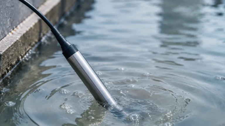
Hydrostatic sensing is based on the measurement of the pressure exerted by a liquid column at a specific point. The relationship is defined by the formula: $P = \rho \cdot g \cdot h$, where $P$ is pressure, $\rho$ is the density of the liquid, $g$ is gravity, and $h$ is the height of the liquid. These sensors are available as submersible probes or externally mounted pressure transmitters at the bottom of the tank. Accuracy depends heavily on the consistency of the fluid's density.
Magnetic Level Gauges
Magnetic level gauges consist of a bypass chamber mounted to the side of a tank. Inside the chamber, a float containing a permanent magnet moves with the liquid level. Outside the chamber, a visual indicator or a transmitter (such as a reed switch chain or magnetostrictive sensor) detects the position of the magnet. This provides both a local visual reading and a remote electronic signal without the risk of leaks associated with traditional sight glasses.
Level Switches
Unlike continuous transmitters, level switches provide point level detection. Common types include:
* Vibrating Fork Switches: A fork vibrates at its natural frequency in air. When submerged in liquid, the frequency shifts, triggering an output.
* Float Switches: A mechanical float moves with the liquid to open or close a circuit.
* Capacitive Switches: These detect changes in electrical capacitance caused by the presence of the media.
Comparative Analysis of Sensing Technologies
Choosing the right technology involves balancing performance requirements with budget constraints. The following table summarizes the typical capabilities of the primary sensing methods used in tank level sensing.
| Technology | Typical Accuracy | Max Range | Contact/Non-contact | Common Applications |
| :— | :— | :— | :— | :— |
| Radar (FMCW) | ±1 mm to ±5 mm | Up to 120 m | Non-contact | Corrosive chemicals, high-pressure vessels, bitumen. |
| Ultrasonic | ±0.25% of range | 0.3 m to 30 m | Non-contact | Water treatment, open channels, plastic tanks. |
| Hydrostatic | ±0.1% to ±0.5% | 0.5 m to 500 m | Contact | Deep wells, fuel tanks, water reservoirs. |
| Guided Wave | ±2 mm to ±5 mm | Up to 75 m | Contact | Small vessels, foaming liquids, interface measurement. |
| Magnetic Gauge | ±5 mm (Transmitter) | Up to 6 m | Contact | Boilers, oil-water separators, toxic storage. |
For a comprehensive look at available hardware and technical specifications, engineers can Review product options and application support on the Welk Main Page.
Application-Specific Selection Criteria
To ensure a reliable installation, several technical factors must be evaluated during the project planning phase.
Media Properties
* Dielectric Constant (εr): For radar and capacitive sensors, the dielectric constant of the material determines the strength of the reflected signal. Materials with low εr (like oils) reflect less energy than those with high εr (like water).
* Viscosity and Coating: Highly viscous or sticky fluids can build up on contact probes (GWR, vibrating forks), leading to false readings. In such cases, non-contact radar or ultrasonic sensors are preferred.
* Density: Hydrostatic sensors require a stable or known density to calculate level. If the density changes due to temperature or mixing, the reading will drift unless compensated.
Process Conditions
* Temperature and Pressure: Ultrasonic sensors are generally limited to atmospheric or low-pressure applications and temperatures below 80°C. Radar sensors can operate in extremes, often exceeding 400°C and 160 bar (16 MPa).
* Vapor and Dust: Heavy steam or chemical vapors can attenuate ultrasonic sound waves. Radar is generally immune to these conditions. However, extremely heavy dust in silos may require high-power 80 GHz radar systems.
* Agitation and Foam: Turbulent surfaces can scatter signals. FMCW radar with advanced signal processing algorithms can filter out noise from agitators. Foam can be problematic for both radar and ultrasonic; guided wave radar is often the best solution for measuring the liquid level beneath a foam layer.
Vessel Geometry
* Internal Obstructions: Pipes, ladders, and heating coils can create "false echoes." Modern sensors allow for "false echo suppression" where the software maps out these static reflections.
* Mounting Nozzles: The height and diameter of the mounting nozzle can affect the signal beam. For ultrasonic and radar, the beam must clear the nozzle edge to prevent interference.

Installation Best Practices for Accuracy
Proper physical installation is as important as selecting the right technology. Poor placement is the leading cause of instrument failure in the field.
1. Avoid the Fill Stream: Never install a level sensor directly in the path of the inflowing material. The turbulence and the physical presence of the stream will cause erratic readings.
2. Vertical Alignment: For non-contact sensors, the transducer face must be perfectly parallel to the liquid surface. A tilt of even a few degrees can significantly reduce the returned signal strength, especially on calm liquid surfaces.
3. Dead Zones (Blocking Distance): Every ultrasonic and radar sensor has a "dead zone" directly beneath the transducer where measurement is impossible. Ensure the sensor is mounted high enough so that the maximum liquid level never enters this zone.
4. Nozzle Considerations: For radar, the antenna should ideally extend slightly past the bottom of the mounting nozzle. If the nozzle is long and narrow, signal reflections from the nozzle walls can degrade accuracy.
5. Submersible Venting: When using hydrostatic submersible transmitters, the vent tube in the cable must remain clear and protected from moisture. A blocked vent tube will prevent the sensor from compensating for changes in atmospheric pressure, leading to errors.
Operational Limitations and Environmental Factors
While modern tank level sensing instruments are robust, they are not universal solutions. Engineers must recognize the following limitations:
* Vacuum Conditions: Ultrasonic sensors cannot function in a vacuum because sound waves require a medium (air/gas) to travel. Radar is the standard choice for vacuum applications.
* Sound Speed Variability: In ultrasonic applications, if the gas space above the liquid is not air (e.g., a nitrogen blanket or CO2), the speed of sound changes. The sensor must be calibrated for the specific gas mixture.
* Reflective Surfaces: In very small metal tanks, radar signals can bounce off the walls multiple times (multipath interference). Using higher frequency radar (e.g., 80 GHz) with a narrower beam angle helps mitigate this.
* Mechanical Wear: Magnetic level gauges and float switches have moving parts. In fluids with high solids content or those prone to crystallization, the floats can become stuck, requiring regular maintenance and flushing.
Frequently Asked Questions (FAQ)
Q: Can I use an ultrasonic sensor to measure the level of fuming nitric acid?
A: It is not recommended. The heavy vapors will likely attenuate the ultrasonic signal, and the corrosive nature of the fumes can damage standard transducers. A radar level meter with a PTFE-sealed antenna is a more reliable choice.
Q: How do I measure the interface between oil and water in a separator tank?
A: Guided Wave Radar (GWR) is the industry standard for interface measurement. The microwave pulse reflects off the upper oil layer (lower dielectric) and continues through to reflect off the water layer (higher dielectric), allowing the transmitter to calculate both levels.
Q: What is the advantage of 80 GHz radar over 26 GHz radar for tank level sensing?
A: 80 GHz radar offers a much narrower beam angle and a shorter wavelength. This allows for better focus, smaller mounting nozzles, and the ability to avoid internal tank obstructions more easily. It also provides better accuracy and a smaller dead zone.
Q: Does the material of the tank (plastic vs. metal) affect the sensor choice?
A: Yes. For example, radar and ultrasonic signals can sometimes pass through plastic tank tops, allowing for mounting outside the tank in certain conditions. Conversely, metal tanks act as Faraday cages for radar, which can be beneficial for containing the signal but requires careful nozzle mounting to avoid internal reflections.
Q: Are hydrostatic sensors suitable for pressurized tanks?
A: Standard hydrostatic sensors measure gauge pressure relative to the atmosphere. In a pressurized tank, you must use a differential pressure (DP) transmitter. One side measures the liquid pressure at the bottom, and the other side measures the gas pressure at the top to cancel out the head pressure.
For further technical guidance on selecting the right instrumentation for your specific industrial environment, visit the Welk Main Page to access detailed product manuals and engineering support.