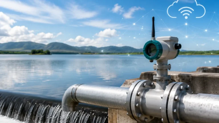
Magmeter
Magmeter
In the landscape of industrial process control, the electromagnetic flow meter, commonly referred to as a magmeter, stands as one of the most versatile and reliable instruments for measuring the flow of conductive liquids. Unlike mechanical flow meters that rely on moving parts such as turbines or paddles, the magmeter utilizes electromagnetic properties to determine flow velocity. This design provides significant advantages, including minimal pressure drop, high accuracy, and the ability to handle corrosive or abrasive fluids.
For engineers managing complex fluid systems, understanding the synergy between flow measurement and level monitoring is essential. While level sensors provide data on the volume contained within a vessel, magmeters provide the critical data on the rate of transfer into or out of that vessel. Together, these instruments allow for precise mass balance and process automation. For more information on comprehensive measurement solutions, you can visit the Main Page of industrial instrumentation providers like Welk.
Understanding the Magmeter Principle
The operation of a magmeter is based on Faraday’s Law of Electromagnetic Induction. This principle states that a voltage is induced when a conductive medium passes through a magnetic field. In the context of a flow meter, the liquid acts as the conductor.
The Mathematical Foundation
The relationship is defined by the equation:
E = B × v × D × k
* E: The induced voltage (signal).
* B: The strength of the magnetic field generated by the coils.
* v: The velocity of the conductive liquid.
* D: The internal diameter of the pipe (the distance between electrodes).
* k: A constant factor specific to the meter’s calibration.
When the liquid flows through the magnetic field generated by the meter's coils, a voltage is generated perpendicular to both the flow direction and the magnetic field. This voltage is directly proportional to the average flow velocity. Because the internal diameter (D) and the magnetic field strength (B) are constant, the induced voltage is a linear representation of the flow velocity. The transmitter then converts this microvolt signal into a standard industrial output, such as 4-20mA, pulse, or digital protocols like Modbus or HART.
Conductivity Requirements
For a magmeter to function, the fluid must have a minimum level of electrical conductivity. Generally, a threshold of 5 μS/cm (microsiemens per centimeter) is required, though some high-sensitivity models can operate at 1 μS/cm. This makes magmeters ideal for water, acids, bases, and slurries, but unsuitable for hydrocarbons, distilled water, or gases, which lack sufficient conductivity.
Essential Components and Materials
A magmeter consists of two primary parts: the sensor (flow tube) and the transmitter (converter). The sensor is installed directly in the pipeline, while the transmitter can be mounted integrally or remotely.
Flow Tube and Liner
The flow tube is typically constructed from non-magnetic stainless steel to prevent interference with the magnetic field. However, because the fluid must be insulated from the metal tube to prevent the induced voltage from shorting out, a liner is applied to the interior. The choice of liner material is critical for chemical compatibility and temperature resistance.
Electrodes
Two or more electrodes are placed opposite each other within the flow tube. These electrodes pick up the induced voltage. Like the liner, electrode material must be chosen based on the corrosiveness of the process fluid.
Selection Table: Liner and Electrode Materials
| Component | Material | Typical Applications | Temperature Range |
| :— | :— | :— | :— |
| Liner | PTFE (Teflon) | Strong acids, bases, high-temp chemicals | -40°C to 180°C |
| | Hard Rubber | Water treatment, general purpose | 0°C to 80°C |
| | Polyurethane | Abrasive slurries, mining, wastewater | -20°C to 60°C |
| | PFA | High purity, pharmaceutical, food | -40°C to 150°C |
| Electrode | SS316L | Low-corrosion liquids, water | N/A |
| | Hastelloy C | Organic/Inorganic chlorides, seawater | N/A |
| | Titanium | Nitric acid, chlorides, seawater | N/A |
| | Tantalum | Highly corrosive acids (Hydrochloric, Sulfuric) | N/A |
Practical Selection Criteria
When specifying a magmeter for a project, several factors must be evaluated to ensure long-term accuracy and device longevity.
1. Fluid Conductivity: Confirm the liquid meets the minimum 5 μS/cm requirement. For example, crude oil and demineralized water cannot be measured with this technology.
2. Pipe Size and Flow Range: The meter size should be chosen based on flow velocity rather than the existing pipe size. Optimal accuracy is typically achieved between 2 m/s and 6 m/s (approx. 6.5 to 20 fps). If the pipe is oversized for the flow rate, a reducer may be necessary to increase velocity.
3. Chemical Compatibility: Use the selection table above to match liners and electrodes to the process media. Improper selection can lead to liner swelling, vacuum collapse, or electrode corrosion.
4. Pressure and Temperature: Ensure the flange rating and liner material can withstand the maximum operating pressure and temperature of the system.
Installation Considerations for Optimal Performance
Proper installation is the most significant factor in magmeter accuracy. Because the meter calculates flow based on velocity profile, the flow must be stable and the pipe must be completely full.
Straight Pipe Runs
To ensure a developed flow profile, magmeters require a specific amount of straight pipe before and after the sensor. Standard guidelines suggest:
* Upstream: 5 x DN (nominal diameter) of straight pipe.
* Downstream: 2 x DN of straight pipe.
If there are heavy disturbances like pumps or partially open valves upstream, the straight run should be increased to 10 x DN.
Mounting Orientation
* Vertical Installation: This is the preferred orientation, with the flow moving upward. This ensures the pipe remains full and prevents air bubbles from being trapped at the electrodes.
* Horizontal Installation: The meter must be installed in a low point of the piping system (a "U" trap) to ensure the pipe is always full. The electrodes must be positioned horizontally (at the 3 and 9 o'clock positions) to avoid interference from air bubbles at the top or sediment at the bottom.
Grounding
Grounding is critical in magmeter installation. Because the induced voltage is extremely small (millivolts), any stray electrical noise in the piping can overwhelm the signal.
* If the pipe is conductive (metal), the meter should be bonded to the flanges.
* If the pipe is non-conductive (PVC, PE, or lined pipe), grounding rings or grounding electrodes must be used to provide a reference point for the fluid.

Limitations and Common Risks
While highly reliable, magmeters are not universal solutions. Engineers should be aware of the following risks:
* Vacuum Conditions: PTFE liners are susceptible to "collapsing" if the pipe experiences a vacuum. In systems where vacuum conditions are possible, PFA liners with mechanical reinforcement or ceramic liners should be specified.
* Entrained Air: Large bubbles or slugs of air will cause the meter to read inaccurately or "hunt" (output fluctuations). Always install the meter at a point in the system where pressure is sufficient to keep gases in solution.
* Coating and Scaling: If the fluid is prone to leaving deposits (like lime or heavy oils), the electrodes can become insulated from the fluid. Some modern transmitters include diagnostic tools to detect electrode coating, but periodic cleaning may be required.
* Non-Conductive Fluids: As previously noted, the technology is physically incapable of measuring non-conductive fluids. In these cases, ultrasonic or vortex flow meters are better alternatives.
Integration with Level Measurement
In industrial automation, flow and level data are often used in tandem. For instance, in a chemical dosing tank, a Welk ultrasonic level sensor might monitor the inventory, while a magmeter on the discharge line ensures the precise volume of chemical is delivered to the process. This redundancy is vital for leak detection; if the level in a tank drops but the magmeter shows no flow, it indicates a potential breach in the containment system.
For engineers looking to optimize their total process control, reviewing various product options and application support is recommended to ensure that both flow and level instruments are calibrated to work in harmony.
Frequently Asked Questions (FAQs)
Q: Can a magmeter measure flow in both directions?
A: Yes, most modern magmeters are bidirectional. They can be configured to measure flow in both directions and provide separate totals for forward and reverse flow.
Q: Does the viscosity of the liquid affect accuracy?
A: Generally, no. Magmeters are independent of viscosity, density, and pressure, provided the flow remains turbulent and the fluid is conductive. This makes them excellent for thick slurries.
Q: How often does a magmeter need calibration?
A: Because there are no moving parts to wear down, magmeters are extremely stable. In many water applications, they only require verification every 2-5 years. However, in corrosive chemical applications, annual checks are recommended to ensure electrode integrity.
Q: What happens if the pipe is only half full?
A: The magmeter will provide an incorrect, usually higher, reading because it assumes the entire cross-sectional area of the pipe is filled with moving liquid. A full pipe is a mandatory requirement for standard electromagnetic flow meters.
By following these engineering guidelines and selecting the appropriate materials for the specific process media, the magmeter provides a long-lasting, low-maintenance solution for industrial flow measurement.