Ultrasonic Transmitter
Ultrasonic Transmitter
In the landscape of industrial process control, the ultrasonic transmitter has established itself as a cornerstone technology for non-contact level measurement. Utilizing high-frequency sound waves to determine the distance to a liquid or solid surface, these instruments provide a reliable, cost-effective solution for a wide range of applications, from municipal water treatment to complex chemical processing. As industries move toward greater automation and precision, understanding the engineering principles, selection criteria, and installation nuances of ultrasonic technology is essential for ensuring operational efficiency.
Measurement Principle: The Physics of Sound
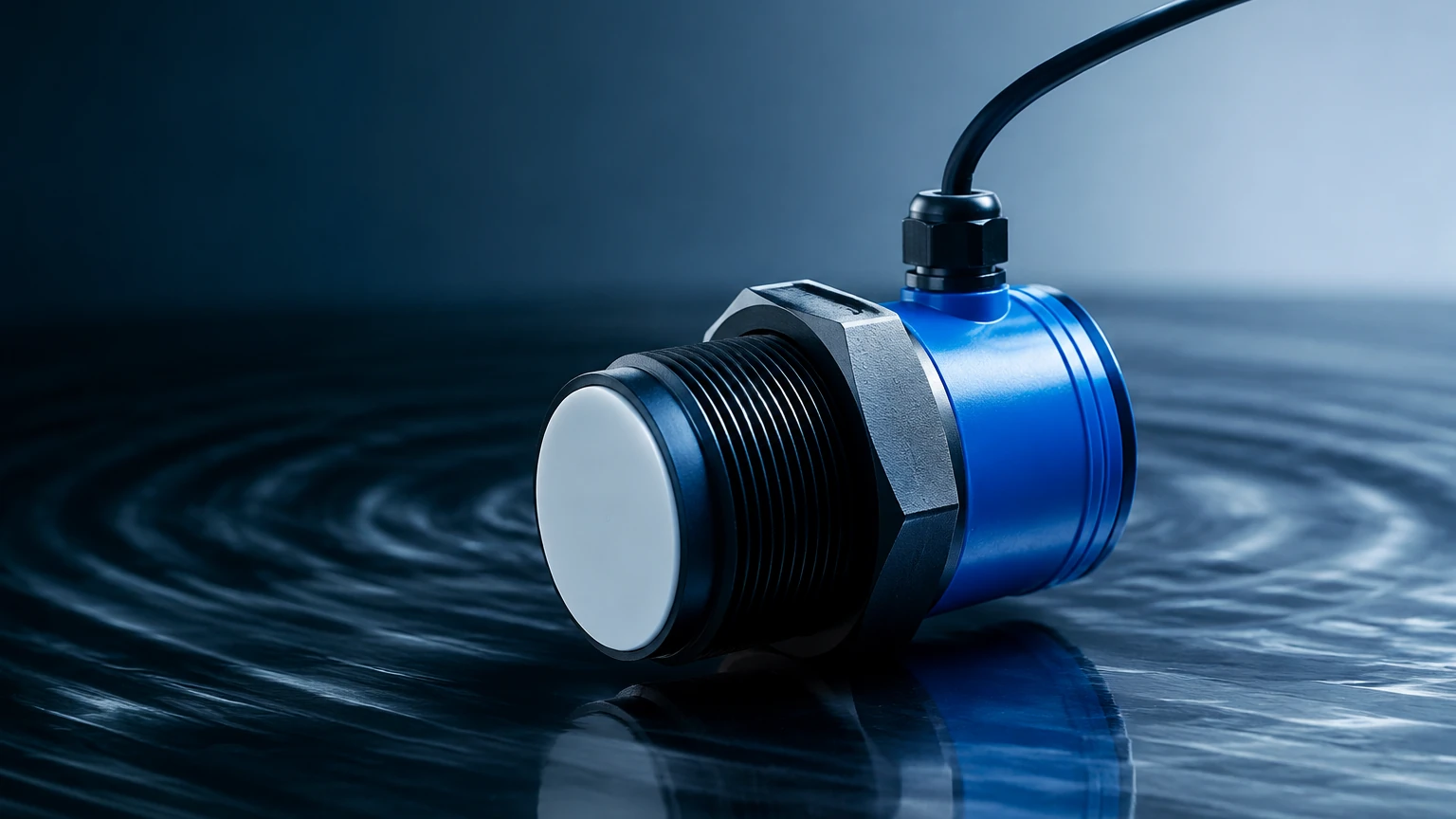
An ultrasonic transmitter operates based on the "Time-of-Flight" (ToF) principle. The device contains a transducer that incorporates a piezoelectric crystal. When energized, this crystal vibrates at a specific frequency, generating a pulse of ultrasonic sound waves—typically ranging from 20 kHz to 70 kHz, which is well above the range of human hearing.
These sound waves travel through the air or gas space above the medium, reflect off the surface of the material, and return to the transducer. The transmitter’s internal electronics act as a high-speed stopwatch, measuring the exact time interval between the emission of the pulse and the reception of the echo.
The distance ($D$) is calculated using the formula:
$$D = \frac{c \times t}{2}$$
Where:
- c is the speed of sound in the medium (typically air).
- t is the total travel time (round trip).
Since the speed of sound is significantly influenced by air temperature—varying by approximately 0.17% per degree Celsius—modern ultrasonic transmitters include integrated temperature sensors. These sensors provide real-time data to the microprocessor, allowing the device to automatically compensate for temperature fluctuations and maintain accuracy. To explore various models and technical specifications, engineers often visit the Main Page of specialized instrument providers to review product options and application support.
Key Components and System Design
A standard industrial ultrasonic transmitter consists of several critical components designed to withstand harsh environments while maintaining signal integrity:
1. The Transducer: Often housed in PVDF, UPVC, or PP, the transducer is the interface between the electronics and the process. Its design determines the beam angle and the frequency of the signal.
2. Signal Processing Electronics: This unit filters out "noise" (stray echoes from tank walls or agitators) and converts the time-of-flight data into a standardized output signal, such as 4-20mA, HART, or Modbus.
3. The Housing: Typically rated IP65 to IP68, the housing protects the electronics from moisture, dust, and chemical vapors. In many industrial settings, explosion-proof or intrinsically safe housings are required for hazardous zones.
Transmitters are generally available in two configurations:
* Integrated (Compact) Type: The transducer and electronics are contained in a single unit. This is ideal for most standard tank level applications where space is at a premium and installation needs to be simplified.
* Remote (Split) Type: The transducer is mounted at the measurement point, while the display and control unit are located in a safe or accessible area, connected by a cable. This is preferred for high-temperature environments or when the measurement point is difficult to access for maintenance.
Technical Selection Criteria
Selecting the correct ultrasonic transmitter requires a thorough analysis of the process environment. Unlike contact-based methods, ultrasonic performance is heavily dependent on the atmospheric conditions between the sensor and the target.
Selection Table: Typical Specifications
| Parameter | Standard Industrial Range | Notes |
| :— | :— | :— |
| Measurement Range | 0.3m to 30m (1ft to 98ft) | Range decreases for solids/powders. |
| Accuracy | ±0.2% to ±0.5% of full scale | Depends on temperature stability. |
| Beam Angle | 5° to 12° | Narrower beams are better for narrow tanks. |
| Operating Temperature | -40°C to +70°C (-40°F to 158°F) | Compensation is required. |
| Output Signal | 4-20mA, RS485, HART | Digital protocols allow for remote config. |
| Dead Zone | 0.2m to 0.6m (0.6ft to 2ft) | Minimum distance required from sensor. |
Practical Installation Considerations
The reliability of an ultrasonic transmitter is often determined more by its installation than by the hardware itself. Engineers must account for several physical factors to ensure the signal returns clearly to the transducer.
1. Managing the Dead Zone (Blanking Distance)
Every ultrasonic transmitter has a "dead zone" or "blanking distance" immediately in front of the transducer face. In this zone, the crystal is still vibrating from the pulse emission and cannot yet "hear" the returning echo. If the liquid level enters this zone, the transmitter will provide an erroneous reading or a "lost echo" error. The sensor must be mounted high enough so that the maximum liquid level never enters the dead zone.
2. Mounting Angle and Position
The transducer must be mounted perpendicular to the liquid surface. Even a slight tilt can cause the sound wave to reflect away from the sensor rather than back to it, resulting in signal loss. Additionally, the sensor should be placed away from the tank walls (typically at least 20cm or 10% of the tank height) to avoid "false echoes" from weld seams, ladders, or structural supports.
3. Avoiding Obstructions
Internal tank components such as agitators, heating coils, and inflow pipes can interfere with the ultrasonic beam. While many modern transmitters feature "false echo suppression" software that allows the device to "learn" and ignore fixed obstructions, it is best practice to provide a clear path for the sound wave.
Limitations and Operational Constraints
While the ultrasonic transmitter is a versatile tool, it is not a universal solution. Certain process conditions can attenuate or distort the sound signal, making ultrasonic measurement impractical:
* Heavy Foam: Foam acts as an acoustic absorber. If a thick layer of foam covers the liquid surface, the sound waves may be absorbed rather than reflected, leading to signal loss. In these cases, radar or hydrostatic transmitters are often preferred.
* Vacuum Conditions: Sound requires a medium (gas/air) to travel. Ultrasonic transmitters cannot function in a vacuum.
* High Pressure: Changes in pressure alter the density of the gas in the tank, which in turn changes the speed of sound. While some compensation is possible, extreme pressure variations can introduce significant errors.
* Extreme Vapors and Dust: High concentrations of heavy vapors (like solvent fumes) or extremely dense dust can change the acoustic impedance of the air, slowing down or scattering the signal.
Comparison with Alternative Technologies
When evaluating level measurement options, it is helpful to compare ultrasonic transmitters against other common technologies used in industrial automation.
| Technology | Advantage | Limitation |
| :— | :— | :— |
| Ultrasonic | Non-contact, low cost, easy to install. | Sensitive to foam, vacuum, and turbulence. |
| Radar (GWR/Non-contact) | Unaffected by vacuum, dust, or vapor. | Higher initial cost. |
| Hydrostatic | Simple, works well in foam. | Contact-based; density changes affect accuracy. |
| Magnetic Gauge | Visual local indication, high pressure/temp. | Requires bypass chamber; mechanical parts. |
Maintenance and Troubleshooting
One of the primary benefits of an ultrasonic transmitter is the lack of moving parts, which significantly reduces maintenance requirements. However, periodic checks are recommended to ensure long-term accuracy:
* Transducer Face Cleaning: In applications involving wastewater or sticky chemicals, condensation or buildup can occur on the transducer face. This should be wiped clean with a soft cloth and mild detergent to prevent signal attenuation.
* Calibration Verification: Annual verification against a manual tape measure is standard practice to ensure the electronics haven't drifted and the temperature compensation remains accurate.
* Signal Strength Monitoring: Most digital transmitters provide a "signal-to-noise ratio" or "echo strength" metric. Monitoring this can provide early warning of changing process conditions, such as the onset of foaming.
Frequently Asked Questions (FAQs)
Q: Can ultrasonic transmitters be used for solids?
A: Yes, but with caveats. Solids like grain, sand, or plastic pellets do not reflect sound as uniformly as liquids. They often form a conical shape (angle of repose) that scatters the signal. For solids, a transmitter with a higher power output and a narrower beam angle is usually required, and the effective range is typically reduced by 50% compared to liquids.
Q: How do I handle measurement in a tank with a heavy agitator?
A: Use the transmitter’s software to perform a "tank map" or "false echo suppression." This allows the device to record the echoes from the agitator blades and ignore them during normal operation. Alternatively, a standpipe (stilling well) can be installed to provide a smooth, isolated liquid surface for measurement.
Q: What is the impact of ambient noise on the transmitter?
A: Most industrial ultrasonic transmitters operate at frequencies far higher than common mechanical noise. However, high-pressure air leaks or certain high-frequency machinery can occasionally interfere. Choosing a transmitter with advanced digital filtering helps mitigate this risk.
Conclusion
The ultrasonic transmitter remains a premier choice for non-contact level measurement due to its balance of performance and affordability. By understanding the fundamental relationship between sound velocity and environmental factors, and by adhering to rigorous installation standards, engineers can achieve highly accurate and reliable data. For those seeking to implement these solutions in water treatment, chemical storage, or industrial automation, consulting a comprehensive technical resource or visiting a professional Main Page for product selection is the recommended next step in the engineering process.