Ultrasonic Flow Transmitter
Ultrasonic Flow Transmitter
In the landscape of industrial process control, the ultrasonic flow transmitter represents a significant advancement over traditional mechanical flow meters. By utilizing acoustic waves to measure the velocity of a fluid, these instruments provide a non-intrusive, highly accurate, and low-maintenance solution for monitoring liquid and gas movement through pipes. For engineers and facility managers in sectors such as water treatment, chemical processing, and oil and gas, understanding the nuances of ultrasonic technology is essential for optimizing system efficiency and ensuring long-term reliability.
As a professional manufacturer, Welk provides a comprehensive range of measurement instruments. While level measurement is a core competency, the underlying physics of ultrasonic technology—sending and receiving high-frequency sound waves—is shared between level sensors and flow transmitters. This guide explores the principles, selection criteria, and installation best practices for ultrasonic flow transmitters in a B2B context.
Measurement Principles of Ultrasonic Flow Technology
Ultrasonic flow transmitters operate based on two primary physical phenomena: Transit-Time and the Doppler Effect. Selecting the correct principle is the first and most critical step in instrument specification.
Transit-Time Method
Transit-time flow meters utilize a pair of transducers that function as both transmitters and receivers. They are mounted on either side of the pipe. One transducer sends a signal downstream, while the other sends a signal upstream.
Because the fluid is moving, the sound wave traveling downstream moves faster than the one traveling upstream. The transmitter measures this time difference (delta-T) with extreme precision. The time difference is directly proportional to the velocity of the fluid. This method is exceptionally accurate for clean liquids with less than 2% total suspended solids (TSS) or aeration.
Doppler Effect Method
The Doppler flow meter operates by transmitting an ultrasonic signal into the flow stream and receiving the reflection of that signal off particles, bubbles, or eddies within the fluid. According to the Doppler principle, the frequency of the reflected signal shifts in proportion to the velocity of the moving particles.
Unlike transit-time meters, Doppler transmitters require a certain level of "discontinuities" (suspended solids or bubbles) to function. They are the preferred choice for wastewater, slurries, and aerated liquids where a transit-time signal would be absorbed or scattered.
Types of Ultrasonic Flow Transmitters
Beyond the measurement principle, these devices are categorized by their physical installation method. Each has distinct advantages depending on the application's budget and infrastructure.
Clamp-On Transmitters
Clamp-on ultrasonic flow transmitters are mounted on the exterior of the pipe. They do not require cutting the pipe or shutting down the process. The transducers are typically secured with stainless steel straps and coupled to the pipe surface using a specialized acoustic gel or epoxy.
* Advantages: No pressure drop, no risk of leakage, easy retrofitting, and zero contact with corrosive or hazardous fluids.
* Applications: Retrofit projects, temporary flow surveys, and high-pressure chemical lines.
Inline (Spool Piece) Transmitters
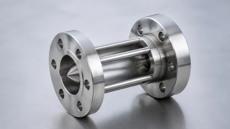
Inline transmitters consist of a factory-calibrated pipe section (spool) with the transducers already integrated. This assembly is bolted into the piping system via flanges.
* Advantages: Higher precision (often up to 0.5% accuracy), factory-guaranteed alignment, and better performance in high-temperature or high-vibration environments.
* Applications: Custody transfer, high-precision chemical dosing, and new plant builds.
Key Evaluation Criteria for Industrial Selection
When evaluating an ultrasonic flow transmitter for a specific project, technical buyers should focus on the following parameters to ensure the device meets the operational demands of the site.
| Parameter | Transit-Time Criteria | Doppler Criteria |
| :— | :— | :— |
| Fluid Type | Clean liquids (water, oils, chemicals) | Dirty liquids (sewage, slurries, aerated water) |
| Suspended Solids | < 2% by volume | > 0.01% (minimum size ~100 microns) |
| Pipe Size | DN15 to DN6000 | DN25 to DN6000 |
| Typical Accuracy | ±0.5% to ±1.0% of rate | ±1.0% to ±2.0% of rate |
| Flow Velocity | 0.1 to 12 m/s | 0.2 to 12 m/s |
| Pipe Material | Carbon steel, Stainless, PVC, Ductile Iron | Most sonic-conductive materials |
Pipe Material and Liners
Ultrasonic waves must pass through the pipe wall to reach the fluid. If the pipe is made of a material that attenuates sound (like certain fiberglass or heavily corroded cast iron), or if there is a loose liner (like unbonded rubber), the signal may be lost. It is vital to confirm the pipe material and the presence of any liners during the procurement phase.
Installation Considerations and Best Practices
The accuracy of an ultrasonic flow transmitter is heavily dependent on the installation environment. Even the most advanced sensor will provide inaccurate data if the flow profile is turbulent or the pipe is not full.
Straight Pipe Run Requirements
To ensure a stable, laminar flow profile, transmitters require a specific length of straight pipe before and after the installation point.
* Upstream: Minimum 10D (10 times the nominal pipe diameter) of straight pipe after a single elbow.
* Downstream: Minimum 5D of straight pipe before the next fitting.
* Increased Distances: If the upstream fitting is a pump or a partially open valve, the requirement may increase to 30D or more.
Transducer Orientation
On horizontal pipes, transducers should be mounted at the 3 o'clock and 9 o'clock positions (the sides of the pipe). Mounting at the top (12 o'clock) can lead to signal interference from air bubbles, while mounting at the bottom (6 o'clock) can cause the signal to be blocked by sediment or scale.
Full Pipe Condition
Ultrasonic meters cannot measure flow in a partially filled pipe accurately. The pipe must be completely full of liquid. In gravity-fed systems, it is common practice to install the transmitter in a "U-trap" or a vertical rising section of the pipe to ensure a permanent liquid seal.

Common Risks and Limitations
While highly versatile, ultrasonic technology is not a universal solution. Engineers must be aware of the following limitations:
1. Signal Attenuation: High-viscosity liquids or fluids with extremely high concentrations of solids can absorb the ultrasonic energy, leading to a "signal loss" error.
2. External Noise: High-frequency vibration from nearby pumps or VFDs (Variable Frequency Drives) can occasionally interfere with the acoustic signal. Shielded cabling and proper grounding are essential.
3. Coupling Degradation: For clamp-on models, the acoustic couplant (grease) can dry out over several years if exposed to high temperatures, requiring periodic maintenance to re-apply the gel.
4. Scaling and Buildup: Significant internal scale buildup on the pipe wall can change the internal diameter used for flow calculations, leading to a systematic error in volumetric flow reporting.
Frequently Asked Questions (FAQ)
Q: Can ultrasonic flow transmitters measure gas flow?
A: Yes, but gas measurement requires specialized high-power transducers and different signal processing than liquid measurement due to the lower density of gases. These are typically used in flare gas or natural gas applications.
Q: How does temperature affect the measurement?
A: The speed of sound in a fluid changes with temperature. Most modern transmitters include a temperature compensation algorithm. For high-precision applications, an external RTD (Resistance Temperature Detector) may be integrated with the transmitter.
Q: Is a clamp-on meter as accurate as an inline meter?
A: Generally, a factory-calibrated inline meter is more accurate because the internal diameter and transducer alignment are fixed. However, for many industrial balance-of-plant applications, the 1% accuracy of a well-installed clamp-on meter is more than sufficient.
Q: What maintenance is required?
A: Since there are no moving parts to wear out, maintenance is minimal. For inline models, periodic calibration checks are recommended. For clamp-on models, the integrity of the mounting straps and the couplant should be inspected annually.
Conclusion
The ultrasonic flow transmitter is a powerful tool for industrial automation, offering a blend of precision and ease of installation that mechanical meters cannot match. By understanding whether a transit-time or Doppler approach is required and adhering to strict installation guidelines regarding straight pipe runs, operators can achieve reliable, long-term flow monitoring.
For organizations looking to integrate these solutions into a broader process control strategy, it is essential to work with a manufacturer that understands the complexities of fluid dynamics. To explore professional-grade measurement hardware and technical specifications, Review product options and application support on our Main Page. Selecting the right instrument today ensures the operational efficiency and safety of your facility for years to come.