Hydraulic Pressure Transducers
Hydraulic Pressure Transducers
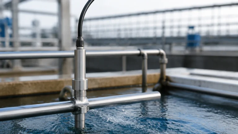
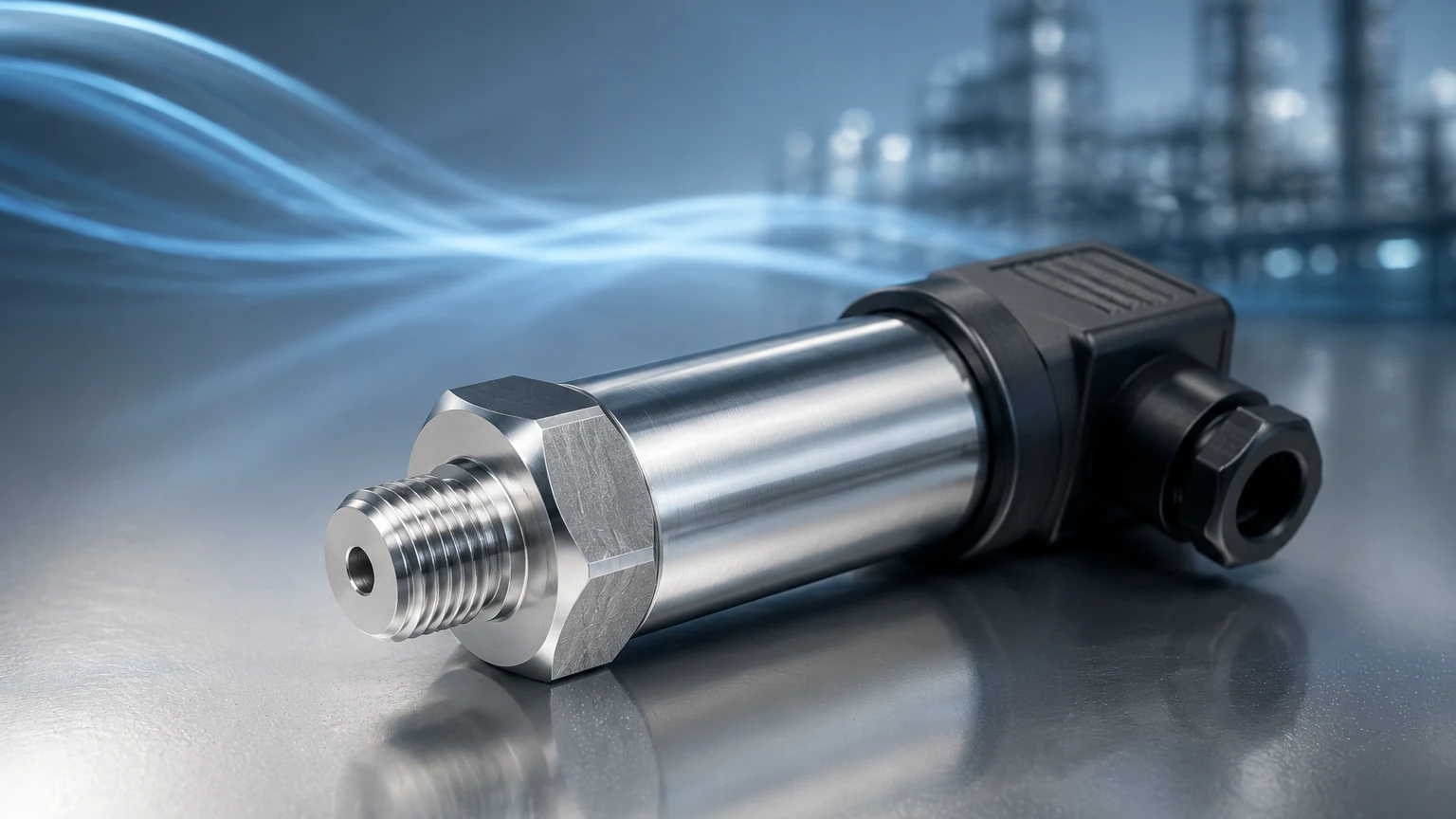
In the realm of industrial automation and process control, the ability to accurately measure fluid force is fundamental. Hydraulic pressure transducers serve as the primary interface between physical hydraulic systems and electronic control units. These devices convert mechanical pressure into a proportional electrical signal, enabling real-time monitoring, safety interlocking, and precise process regulation. For engineers and system integrators, understanding the nuances of transducer technology is essential for ensuring the longevity and reliability of hydraulic machinery and fluid storage systems.
Measurement Principles of Hydraulic Pressure Transducers
Before selecting a sensor for a specific application, it is necessary to understand the underlying physics that allow these devices to function. Most hydraulic pressure transducers rely on the elastic deformation of a sensing element, typically a diaphragm, which responds to the force exerted by the hydraulic fluid.
Piezoresistive Sensing
This is one of the most common technologies used in modern transducers. A piezoresistive sensor consists of a silicon or ceramic diaphragm with integrated resistors. When hydraulic pressure is applied, the diaphragm flexes, changing the electrical resistance of the resistors (the piezoresistive effect). This change is measured via a Wheatstone bridge circuit. Piezoresistive sensors are known for their high sensitivity and stability, making them ideal for low-to-medium pressure applications.
Thin-Film Strain Gauge
For high-pressure hydraulic systems, thin-film strain gauge technology is often preferred. In this design, metal strain gauges are sputtered directly onto a stainless steel diaphragm. As pressure increases, the diaphragm deforms, stretching the strain gauges and altering their resistance. Because the gauges are molecularly bonded to the substrate, these sensors offer excellent resistance to shock, vibration, and pressure spikes, which are common in heavy industrial hydraulics.
Ceramic Capacitive Sensing
Capacitive transducers measure the change in electrical capacitance between a flexible ceramic diaphragm and a fixed base plate. As pressure moves the diaphragm closer to the base, the capacitance increases. Ceramic sensors are highly resistant to aggressive chemicals and mechanical wear, though they may be more sensitive to temperature fluctuations than their thin-film counterparts.
The Role of Pressure Transducers in Level Measurement
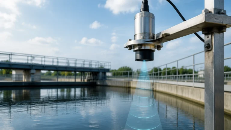
While often associated with power hydraulics (such as pistons and pumps), hydraulic pressure transducers are also the core component of hydrostatic level measurement. By measuring the pressure exerted by a static column of liquid, the height of the fluid can be calculated using the formula:
Height (h) = Pressure (P) / (Density (ρ) × Gravity (g))
Welk provides a range of instruments based on these principles, ensuring that whether the application involves a high-pressure hydraulic line or a deep water tank, the measurement remains accurate. For those looking to integrate these sensors into broader automation frameworks, you can Review product options and application support to find the specific configuration required for your project.
Key Evaluation Criteria for Selection
Selecting the wrong transducer can lead to premature failure or inaccurate data. Engineers should evaluate the following parameters during the specification phase:
Pressure Range and Overpressure
The nominal pressure range should be selected so that the typical operating pressure falls within the middle 50% to 75% of the sensor’s range. However, hydraulic systems are prone to "water hammer" or rapid pressure spikes. It is vital to confirm the sensor’s proof pressure (the maximum pressure it can withstand without permanent damage) and burst pressure (the point of mechanical failure).
Signal Output
* 4-20 mA: The industry standard for long-distance transmission, as it is highly resistant to electromagnetic interference (EMI).
* 0-10 V / 1-5 V: Common in laboratory settings or short-distance industrial applications where high-impedance inputs are available.
* Digital (Modbus/CANopen): Increasingly popular in "Industry 4.0" setups for transmitting diagnostic data alongside the pressure reading.
Material Compatibility
The wetted parts—the components of the transducer that touch the fluid—must be compatible with the hydraulic media. While 316L stainless steel is standard, specialized synthetic oils or corrosive chemicals may require Hastelloy or ceramic diaphragms.
Selection Table: Comparison of Transducer Types
| Feature | Piezoresistive | Thin-Film Strain Gauge | Ceramic Capacitive |
| :— | :— | :— | :— |
| Typical Range | 0.1 to 400 bar | 10 to 2,000+ bar | 0.05 to 100 bar |
| Accuracy | High (0.1% to 0.5%) | Moderate (0.2% to 1.0%) | High (0.1% to 0.5%) |
| Durability | Moderate | Very High | High (Chemical) |
| Best Use Case | General Industrial | Mobile Hydraulics/Heavy Machinery | Chemical/Water Treatment |
Installation Considerations
Proper installation is as critical as the sensor's specifications. Incorrect mounting can introduce measurement errors or lead to mechanical fatigue.
1. Orientation: While most transducers can be mounted in any orientation, they are often calibrated in a vertical position. Mounting horizontally may cause a slight "zero shift" due to the weight of the fluid on the diaphragm, which must be compensated for during commissioning.
2. Pressure Snubbers: In systems with rapid valve closures, use a pressure snubber. This is a small fitting that restricts the flow of fluid to the sensor, dampening the impact of pressure spikes without affecting the steady-state accuracy.
3. Venting: For gauge pressure transducers (which measure pressure relative to the atmosphere), the back of the diaphragm must be vented. Ensure the vent tube or hole is protected from moisture and dust ingress.
4. Electrical Grounding: Ensure the transducer housing is properly grounded to prevent ground loops and protect against electrical noise from nearby motors or VFDs.
Common Risks and Limitations
Despite their robustness, hydraulic pressure transducers face several environmental and operational challenges:
* Temperature Drift: All sensors are affected by temperature changes. High-quality transducers include internal temperature compensation, but extreme heat can still cause the signal to drift. If the process fluid is exceptionally hot, use a cooling element or a capillary tube to isolate the sensor from the heat source.
* Cavitation: If the pressure drops below the vapor pressure of the fluid, bubbles can form and collapse violently against the sensor diaphragm, causing pitting and eventual failure.
* Media Clogging: In applications involving viscous fluids or suspended solids, the pressure port can become clogged. In these instances, a "flush diaphragm" design—where the sensing surface is level with the process connection—is recommended over a standard recessed port.
Maintenance and Troubleshooting
To maintain system integrity, a routine maintenance schedule should be established. This includes:
* Zero-Point Verification: Periodically check the sensor output when the system is at atmospheric pressure. A significant shift usually indicates diaphragm fatigue or internal damage.
* Cable Inspection: In mobile hydraulic applications, cables are frequently damaged by debris or excessive bending. Check for cracks in the jacket and moisture in the connectors.
* Calibration: Most industrial standards require annual or biennial calibration against a traceable reference standard to ensure accuracy remains within the specified tolerance.
Frequently Asked Questions (FAQ)
Q: What is the difference between a pressure transmitter and a pressure transducer?
A: Historically, a "transducer" referred to a device with a voltage output, while a "transmitter" referred to a device with a current output (4-20 mA). Today, the terms are often used interchangeably in B2B contexts, though "transmitter" is more common in process industries.
Q: Can I use a hydraulic pressure transducer for gas applications?
A: Generally, yes, provided the materials are compatible. However, gas is compressible and behaves differently under dynamic conditions. Ensure the sensor is rated for the specific gas and that safety protocols for high-pressure gas are followed.
Q: How do I handle pressure spikes that exceed the sensor's rating?
A: The most effective method is using a mechanical snubber or a capillary line. Additionally, selecting a sensor with a higher overpressure rating (e.g., 4x the working pressure) can provide a safety buffer.
Q: Why is my 4-20 mA signal reading 0 mA?
A: A 0 mA reading typically indicates a break in the loop, such as a cut wire or a failed power supply. A functioning but "empty" sensor should read 4 mA at zero pressure.
Conclusion for Project Planning
When planning a project involving hydraulic pressure transducers, it is essential to confirm the fluid properties, the expected dynamic range of the system, and the environmental conditions of the installation site. By aligning the sensing technology with the specific demands of the application—whether it be the ruggedness of a thin-film gauge for construction equipment or the precision of a piezoresistive sensor for hydrostatic level—operators can ensure long-term system stability. For detailed technical specifications and support in selecting the right instrumentation for your facility, visit the Main Page to explore the full range of available solutions.