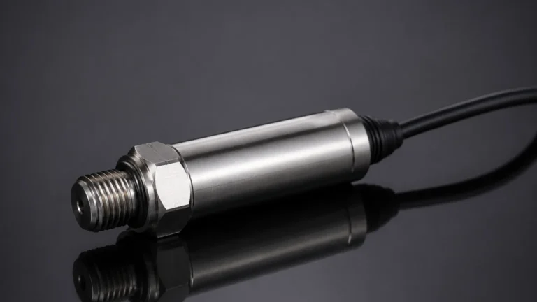
Gas Flow Sensors
Gas Flow Sensors
Gas flow sensors are fundamental components in industrial process control, environmental monitoring, and energy management. Unlike liquid flow measurement, gas measurement presents unique challenges due to the compressibility of the medium, variations in density with temperature and pressure, and the potential for phase changes. For engineers and facility managers, selecting the correct gas flow technology is critical for ensuring process efficiency, safety, and regulatory compliance.
In the broader context of industrial automation, gas flow measurement often works in tandem with other instrumentation. For example, while level measurement instruments—such as those detailed on our Main Page—monitor the volume of liquids or solids in a vessel, gas flow sensors track the consumption or movement of gases used for tank blanketing, combustion, or aeration. Understanding the physics behind these sensors is the first step toward a successful installation.
Fundamental Principles of Gas Flow Measurement
Gas flow measurement is generally categorized into two types: volumetric flow and mass flow. Because gases are highly compressible, volumetric flow rates (e.g., cubic meters per hour) can change significantly with fluctuations in pressure and temperature. Consequently, many industrial applications prioritize mass flow measurement (e.g., kilograms per hour) or "standardized" volumetric flow, which refers to the volume the gas would occupy at a specific reference temperature and pressure.
Thermal Mass Transfer
Thermal gas flow sensors operate on the principle of heat transfer. When a gas flows over a heated surface, it carries away heat. The rate of heat loss is proportional to the mass flow rate of the gas. There are two primary methods used in this category:
1. Constant Temperature Differential: The sensor maintains a fixed temperature difference between a heated element and the ambient gas. The electrical power required to maintain this difference is measured and converted into a mass flow reading.
2. Constant Power: A fixed amount of power is supplied to the heating element, and the resulting temperature difference between the element and the gas is measured.
Differential Pressure (DP)
Based on Bernoulli’s equation, differential pressure sensors introduce a restriction in the flow path (such as an orifice plate, Venturi tube, or Pitot tube). As the gas passes through the restriction, its velocity increases and its pressure decreases. The difference in pressure between the upstream and downstream points is proportional to the square of the flow velocity.
Vortex Shedding
This principle relies on the Karman Vortex Street effect. When a gas flows past a non-streamlined "bluff body" placed in the pipe, alternating vortices (swirls) are shed from the sides of the body. The frequency at which these vortices are shed is directly proportional to the velocity of the gas flow. This frequency is detected by a sensor, typically a piezoelectric crystal.
Ultrasonic Transit-Time
Ultrasonic sensors use sound waves to determine flow velocity. In the transit-time method, two transducers send ultrasonic pulses back and forth across the pipe. A pulse traveling with the flow moves faster than a pulse traveling against it. The difference in time is used to calculate the gas velocity.
Primary Types of Gas Flow Sensors
1. Thermal Mass Flow Meters
These are highly popular for clean gas applications. They measure mass flow directly without needing external pressure or temperature compensation.
* Advantages: High sensitivity to low flow rates, no moving parts, and excellent turndown ratios (often 100:1).
* Best For: Nitrogen blanketing, compressed air monitoring, and leak detection.
2. Vortex Flow Meters
Vortex meters are known for their durability and lack of moving parts. They are particularly effective for high-velocity gas and steam applications.
* Advantages: High reliability, low maintenance, and wide temperature/pressure range.
* Best For: Natural gas measurement and saturated or superheated steam.
3. Coriolis Mass Flow Meters
Coriolis meters measure mass flow by detecting the inertia of the gas as it flows through vibrating tubes. While more expensive, they provide the highest accuracy.
* Advantages: Direct mass flow measurement, extremely high accuracy (±0.5% or better), and immunity to gas composition changes.
* Best For: High-value gases and chemical dosing where precision is paramount.
4. Turbine Flow Meters
These sensors use a multi-bladed rotor that spins as gas passes through. The rotational speed of the rotor is proportional to the gas velocity.
* Advantages: High accuracy and excellent repeatability for steady flow conditions.
* Best For: Custody transfer of natural gas.
Technical Selection Criteria for Industrial Applications
Choosing the right gas flow sensor requires a detailed analysis of the process conditions. The following table provides a comparative overview of common technologies:
| Technology | Accuracy (Typical) | Turndown Ratio | Pressure Drop | Primary Limitation |
| :— | :— | :— | :— | :— |
| Thermal Mass | ±1.0% of Rate | 100:1 | Very Low | Moisture/Droplets |
| Vortex | ±1.0% of Rate | 20:1 | Medium | Low-velocity cutoff |
| Coriolis | ±0.5% of Rate | 100:1 | High | High initial cost |
| Differential Pressure | ±2.0% of Span | 4:1 | High | Limited rangeability |
| Ultrasonic | ±1.0% of Rate | 50:1 | Negligible | Gas composition changes |
Key Evaluation Factors:
* Gas Composition: Is the gas a single component (e.g., Nitrogen) or a mixture (e.g., Biogas)? Thermal mass meters must be calibrated for the specific gas species.
* Flow Range: Determine the minimum and maximum expected flow rates. If the range is wide, a high turndown ratio is required.
* Process Temperature and Pressure: Ensure the sensor body and electronics can withstand the maximum operating conditions. For high-pressure gas, Coriolis or DP meters are often preferred.
* Allowable Pressure Drop: Some sensors, like orifice plates, cause a significant permanent pressure loss, which increases energy costs for compressors.
Installation Considerations and Piping Requirements
Proper installation is as critical as sensor selection. Most gas flow sensors require a fully developed flow profile to provide accurate readings.
1. Straight Pipe Runs: To eliminate turbulence caused by elbows, valves, or reducers, sensors typically require a minimum of 10 to 20 diameters of straight pipe upstream and 5 diameters downstream. If space is limited, flow conditioners (perforated plates) may be used.
2. Orientation: For gases, sensors are often mounted on the top or side of a horizontal pipe to prevent moisture or condensate from accumulating on the sensor element.
3. Filtration: Many gas flow sensors, particularly thermal and turbine types, are sensitive to particulates. Installing a filter or strainer upstream can prevent mechanical damage or measurement drift.
4. Vibration and Noise: Ultrasonic and vortex meters can be affected by mechanical vibrations or acoustic noise from nearby valves. Proper piping support and isolation are necessary.
Limitations and Operational Risks
While gas flow sensors are highly advanced, they are not immune to environmental and process-related errors.
* Moisture and Condensation: In thermal mass meters, water droplets hitting the heated sensor can be interpreted as a massive surge in gas flow because water carries away heat much more effectively than gas. This often leads to "spiking" in the data.
* Gas Density Variations: For volumetric meters (like DP or Turbine), any change in pressure or temperature that is not compensated for will result in a direct error in the calculated mass flow.
* Calibration Drift: Over time, sensors may drift due to coating, corrosion, or electronic aging. Regular field verification or factory recalibration is essential for maintaining accuracy.
* Non-Conductive Gases: Unlike electromagnetic flow meters used for liquids, gas flow measurement cannot rely on conductivity, limiting the technology options to mechanical, thermal, or acoustic methods.
Synergy Between Gas Flow and Level Measurement
In many industrial settings, gas flow and level measurement are two sides of the same coin. For instance, in a chemical storage tank, a radar level meter monitors the liquid level to prevent overfills. Simultaneously, a gas flow sensor monitors the nitrogen gas used to "blanket" the tank. This nitrogen prevents the liquid from reacting with oxygen or moisture in the air.
If the level meter shows a rapid drop in liquid, the gas flow sensor should show a corresponding increase in nitrogen flow to fill the void. A discrepancy between these two readings could indicate a leak in the tank or a malfunction in the gas supply system. Integrating these two data points provides a more comprehensive view of vessel integrity and process safety.
Frequently Asked Questions (FAQ)
Q: Can I use a liquid flow meter for gas?
A: Generally, no. Most liquid flow meters, such as electromagnetic (mag) meters, require a conductive fluid and will not work with gases. Others, like turbine meters, are calibrated specifically for the density and viscosity of liquids and will provide highly inaccurate readings if used for gas without significant modification.
Q: What is the difference between Nm³/h and m³/h?
A: m³/h is the actual volume flow at the current operating temperature and pressure. Nm³/h (Normal cubic meters per hour) is the volume flow corrected to standard conditions (usually 0°C and 1.01325 bar). This allows for consistent measurement regardless of process fluctuations.
Q: Why is my thermal mass flow meter reading high when the gas is wet?
A: Thermal mass meters measure the rate of heat dissipation. Because water has a much higher heat capacity than gas, even small droplets of moisture hitting the sensor will pull away a large amount of heat, causing the sensor to report a much higher flow rate than is actually present.
Q: How often should gas flow sensors be calibrated?
A: This depends on the criticality of the process and the gas type. For custody transfer (buying/selling gas), annual calibration is standard. For general process monitoring, a check every 2 to 3 years may be sufficient, provided that the gas is clean and non-corrosive.
Q: Do gas flow sensors require pressure compensation?
A: Thermal mass and Coriolis meters measure mass flow directly and do not require external pressure compensation. However, Vortex, Turbine, and Differential Pressure meters measure velocity or volume and require simultaneous pressure and temperature measurements to calculate mass or standardized flow accurately.