Ultrasonic Level Gauge
Ultrasonic Level Gauge
In the landscape of industrial process control, the ultrasonic level gauge has established itself as a cornerstone technology for non-contact level measurement. As a versatile solution for monitoring liquids and certain bulk solids, these instruments provide a balance of accuracy, reliability, and cost-effectiveness. For plant engineers and system integrators, understanding the underlying physics, selection criteria, and installation nuances is essential for ensuring long-term operational success.
Welk, a professional manufacturer of industrial level measurement instruments, provides a wide array of ultrasonic solutions designed to meet the rigorous demands of water treatment, chemical processing, and industrial automation. To explore the full spectrum of instrumentation available, professionals can Review product options and application support on our Main Page.
Measurement Principle: The Physics of Sound
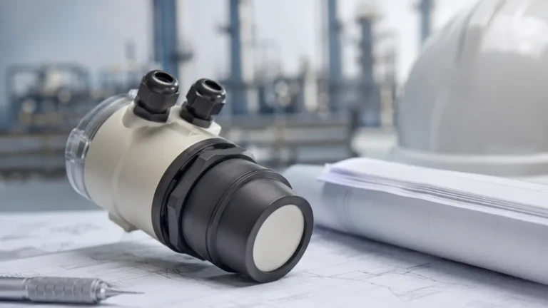
The operation of an ultrasonic level gauge is based on the "Time-of-Flight" (ToF) principle. The instrument consists of a transducer containing a piezoelectric crystal that serves both as a transmitter and a receiver.
The Pulse-Echo Cycle
When energized, the transducer emits a burst of high-frequency ultrasonic sound waves (typically ranging from 20 kHz to 70 kHz, depending on the required range). These waves travel through the air or gas space above the medium, reflect off the surface of the material, and return to the transducer.
The gauge calculates the distance ($D$) between the sensor face and the material surface using the following formula:
$$D = \frac{c \times t}{2}$$
Where:
* $c$ is the speed of sound in the medium (usually air).
* $t$ is the total elapsed time from pulse emission to echo reception.
Since the height of the vessel ($H$) is a known fixed value, the level of the material ($L$) is derived by subtracting the measured distance from the total height: $L = H – D$.
The Role of Temperature Compensation
The speed of sound is not constant; it fluctuates based on the temperature of the medium through which it travels. In air at sea level, the speed of sound increases by approximately 0.6 meters per second for every degree Celsius increase in temperature. To maintain accuracy, modern ultrasonic level gauges include an integrated temperature sensor. This sensor provides real-time data to the microprocessor, which automatically adjusts the distance calculation to account for thermal variations in the vapor space.
Key Evaluation Criteria for Selection
Selecting the correct ultrasonic level gauge requires a thorough analysis of the application environment. A mismatch between the instrument specifications and the process conditions is the leading cause of measurement failure.
1. Measurement Range and Dead Zone
Every ultrasonic sensor has a "dead zone" (also known as the blocking distance) immediately below the transducer face. In this region, the transducer is still vibrating from the initial pulse and cannot accurately detect a returning echo. Typical dead zones range from 0.25m to 0.8m. If the liquid level enters this zone, the gauge will provide an erroneous reading. Therefore, the sensor must be mounted high enough to ensure the maximum liquid level never reaches the dead zone.
2. Beam Angle and Obstructions
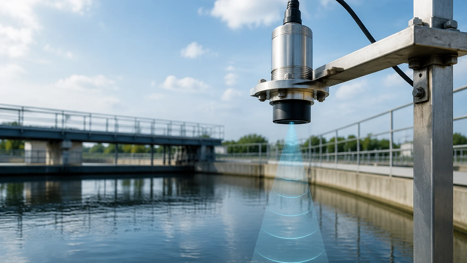
The ultrasonic pulse does not travel in a straight line but spreads out in a conical shape, known as the beam angle (usually between 5° and 12°). Any internal tank structures—such as ladders, pipes, or agitators—that fall within this cone will create "false echoes." While advanced software can often filter these out through "false echo suppression," it is best practice to select a sensor with a narrower beam angle for narrow tanks or those with complex internals.
3. Material Compatibility
For corrosive applications, such as acid or alkali storage, the wetted parts of the sensor must be resistant to chemical attack. Standard sensors often use ABS or PVC, while specialized versions utilize PVDF (Polyvinylidene Fluoride) or PTFE (Polytetrafluoroethylene) to ensure longevity in harsh environments.
4. Output and Connectivity
Industrial automation requires seamless integration. Most ultrasonic level gauges offer a standard 4-20mA analog output, often coupled with digital protocols like HART, Modbus RTB, or RS485. This allows for remote monitoring and integration into PLC/SCADA systems.
Selection Table: Industrial Ultrasonic Level Gauges
The following table provides a general comparison of common ultrasonic configurations used in industrial settings.
| Specification | Compact Series | Extended Range Series | Chemical-Resistant Series |
| :— | :— | :— | :— |
| Measuring Range | 0.4m – 10m | 0.5m – 20m | 0.3m – 8m |
| Dead Zone | ≤ 0.3m | ≤ 0.6m | ≤ 0.35m |
| Accuracy | ±0.25% of Full Scale | ±0.2% of Full Scale | ±0.5% of Full Scale |
| Beam Angle | 8° – 10° | 5° – 8° | 10° – 12° |
| Process Temp. | -20°C to +60°C | -40°C to +80°C | -20°C to +70°C |
| Housing Material | ABS / Plastic | Cast Aluminum | PVDF / PTFE |
| Protection Rate | IP65 / IP67 | IP67 / IP68 | IP67 / IP68 |
Critical Installation Guidelines
Proper installation is the most significant factor in the performance of an ultrasonic level gauge. Engineers should adhere to the following checklists during the design and commissioning phases.
Mounting Position
* Avoid the Center: In cylindrical tanks with domed tops, do not mount the sensor in the exact center. This can cause multiple reflections to converge at the sensor, creating a "parabolic effect" that confuses the signal processor.
* Distance from Wall: The sensor should be mounted at a distance from the tank wall equal to at least 1/6th of the tank height to prevent interference from wall seams or welds.
* Perpendicularity: The transducer face must be perfectly parallel to the liquid surface. A tilt of even a few degrees can cause the signal to bounce away from the sensor rather than returning to it.
Avoiding Interference
* Fill Stream: Never mount the sensor directly above the inlet pipe. The falling liquid will obstruct the ultrasonic pulse and cause erratic readings.
* Agitators: If the tank has an agitator, the sensor should be positioned where the blades create the least amount of surface turbulence. Software filtering can be used to ignore the periodic echo from the moving blades.
Standpipe Usage
In applications with heavy foam or extreme turbulence, a standpipe (stilling well) can be used. The pipe acts as a guide for the ultrasonic wave and provides a calm surface for measurement. However, the pipe must be smooth and free of burrs on the inside to prevent signal degradation.
Environmental Limitations and Mitigation
While ultrasonic level gauges are robust, certain environmental factors can attenuate the signal or affect the speed of sound accuracy.
Vacuum and Pressure
Ultrasonic waves require a medium (gas) to travel. Therefore, ultrasonic gauges cannot function in a vacuum. High-pressure environments also change the density of the gas, which significantly alters the speed of sound. For applications exceeding 0.3 MPa (3 bar), radar level meters are generally preferred over ultrasonic types.
Heavy Dust, Steam, and Foam
* Dust and Steam: Large amounts of airborne dust (in silos) or thick steam (in hot water tanks) can absorb the ultrasonic energy, weakening the echo. In these cases, a higher-power transducer with a lower frequency is required to penetrate the atmosphere.
* Foam: Soft, airy foam is an excellent sound absorber. If a thick layer of foam covers the liquid, the ultrasonic pulse may not reflect at all, resulting in a "Loss of Echo" error. For heavy foam applications, contact-type measurement or high-frequency radar is often more reliable.
Gas Composition
If the vapor space consists of gases other than air (e.g., Nitrogen, Carbon Dioxide, or Methane), the speed of sound will differ significantly from standard calibrations. For example, the speed of sound in $CO_2$ is much slower than in air. If the gas concentration is constant, the gauge can be calibrated with a custom sound velocity; however, if the gas mixture fluctuates, ultrasonic measurement may become unreliable.
Comparison with Other Level Technologies
To provide a complete engineering reference, it is helpful to compare the ultrasonic level gauge against its primary alternatives.
* Ultrasonic vs. Radar: Radar uses electromagnetic waves rather than sound. Radar is unaffected by vacuum, temperature fluctuations, or gas composition, making it superior for high-pressure/high-temperature process vessels. However, ultrasonic remains the more cost-effective choice for simple water and wastewater applications.
* Ultrasonic vs. Hydrostatic: Hydrostatic sensors measure the pressure exerted by the liquid column. While highly accurate, they are contact-based and can be affected by changes in liquid density. Ultrasonic gauges are preferred when the liquid is corrosive, contains solids that might clog a pressure diaphragm, or when a non-contact solution is required for hygiene.
Frequently Asked Questions (FAQs)
Q: Can an ultrasonic level gauge be used to measure solids?
A: Yes, but with limitations. Solids like grain, sand, or plastic pellets do not reflect sound as efficiently as liquids. They often form a conical pile which reflects the signal away from the sensor. For solids, a high-power sensor with a very narrow beam angle and a swiveling mounting flange is usually necessary.
Q: What is the maximum distance an ultrasonic gauge can measure?
A: Most industrial ultrasonic gauges are effective up to 15-20 meters. Beyond this range, the sound wave attenuation in the air becomes too great for reliable detection, and radar technology is typically recommended.
Q: How does wind affect the measurement in open-air applications?
A: In outdoor sumps or open channels, strong winds can "blow" the ultrasonic pulse away, causing signal loss. In these environments, using a protective shroud or a standpipe can help stabilize the measurement.
Q: Is periodic maintenance required?
A: Because there are no moving parts, maintenance is minimal. However, in humid or dusty environments, the transducer face should be checked periodically for condensation or buildup, which can be wiped away with a soft cloth.
Conclusion
The ultrasonic level gauge remains a premier choice for non-contact level monitoring due to its lack of moving parts and ease of integration. By carefully considering the dead zone, beam angle, and environmental factors like foam and gas composition, engineers can deploy these instruments to achieve high-precision results in diverse industrial applications.
For those seeking specific product configurations or technical consultation on complex installations, Welk offers comprehensive support and customized OEM/ODM services. To learn more about our full range of level measurement solutions, please visit our Main Page to Review product options and application support.