Conductivity Sensor for Water
Conductivity Sensor for Water
In industrial process control and water treatment, the conductivity sensor for water serves as a fundamental analytical tool. It provides a real-time measurement of a liquid's ability to conduct an electrical current, which is directly proportional to the concentration of dissolved ionized solids (salts, acids, or bases) within the solution. While often used as a proxy for Total Dissolved Solids (TDS), conductivity measurement is a distinct electrochemical process that requires specific hardware configurations based on the water quality and environmental conditions.
For engineers and plant managers, selecting the correct conductivity sensor for water is critical for maintaining boiler efficiency, ensuring the purity of pharmaceutical-grade water, or managing the chemical dosing in wastewater treatment plants. This guide examines the underlying physics of conductivity measurement, compares available technologies, and provides technical benchmarks for industrial selection.
Measurement Principles of Conductivity Sensors
To effectively deploy a conductivity sensor for water, one must understand the two primary methods used to capture this data: contacting (electrolytic) and inductive (toroidal) measurement.
Contacting Conductivity Measurement
Contacting sensors utilize electrodes that come into direct physical contact with the water. A known voltage is applied between two or more electrodes, and the resulting current is measured. According to Ohm’s Law, the resistance of the solution can be calculated, and its reciprocal is the conductance.
To standardize this measurement regardless of the sensor's physical size, a "Cell Constant" ($k$) is used. The cell constant is the ratio of the distance between the electrodes to the area of the electrodes.
* Low Cell Constants ($k=0.01$ to $0.1$): Used for high-purity water where ions are scarce.
* High Cell Constants ($k=1.0$ to $10$): Used for brackish or wastewater where ion concentration is high.
Inductive (Toroidal) Conductivity Measurement
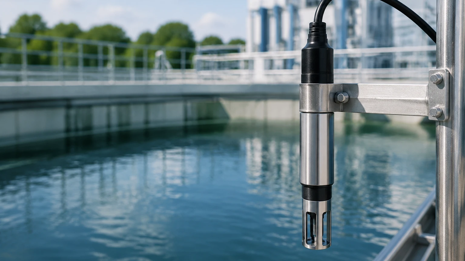
Inductive sensors, often referred to as toroidal sensors, do not use electrodes. Instead, they consist of two wire-wound metal toroids encased in a plastic or ceramic housing. One coil acts as a transmitter, creating an alternating magnetic field that induces a current in the surrounding liquid. The second coil acts as a receiver, measuring the magnitude of this induced current.
Because the sensing elements are completely isolated from the process fluid, inductive sensors are immune to electrode coating, polarization, and corrosion, making them the preferred choice for aggressive chemical applications or high-fouling environments.
Key Evaluation Criteria for Industrial Applications
When evaluating a conductivity sensor for water, technical specifications must align with the specific chemical and physical properties of the process stream. The following criteria are foundational to sensor longevity and accuracy.
Measurement Range and Sensitivity
Conductivity can span several orders of magnitude, from $0.055 \text{ } \mu S/cm$ in ultrapure water to over $1,000 \text{ } mS/cm$ in concentrated acids. A sensor designed for ultrapure water will saturate and fail to provide meaningful data in a seawater application. Conversely, a toroidal sensor lacks the sensitivity required for sub-microSiemens measurements.
Temperature Compensation
Conductivity is highly temperature-dependent; as temperature rises, the mobility of ions increases, typically raising conductivity by approximately $2\%$ per degree Celsius. Reliable sensors must include an integrated temperature element (such as a Pt100 or Pt1000 RTD) to provide Temperature Compensated (TC) readings, usually referenced to $25^{\circ}C$.
Material Compatibility
For contacting sensors, the electrode material must be chemically inert relative to the fluid. Common materials include:
* 316L Stainless Steel: Standard for general water and high-purity applications.
* Graphite: Excellent for high-range measurements and resistant to many chemicals.
* Titanium: Used in highly corrosive or seawater environments.
For inductive sensors, the outer body material (PEEK, PFA, or Polypropylene) determines the sensor's resistance to temperature and chemical attack.
Selection Guide: Application vs. Technology
The following table provides a practical reference for selecting a conductivity sensor for water based on common industrial scenarios.
| Application | Typical Conductivity Range | Recommended Sensor Type | Common Cell Constant ($k$) |
| :— | :— | :— | :— |
| Ultrapure Water (RO/DI) | $0.055$ – $10 \text{ } \mu S/cm$ | 2-Pole Contacting (SS) | $0.01$ or $0.1$ |
| Potable Water Treatment | $50$ – $1,000 \text{ } \mu S/cm$ | 2-Pole or 4-Pole Contacting | $1.0$ |
| Cooling Tower Blowdown | $1,000$ – $5,000 \text{ } \mu S/cm$ | 4-Pole Contacting or Toroidal | $1.0$ |
| Wastewater / Effluent | $10$ – $20,000 \text{ } \mu S/cm$ | Toroidal (Inductive) | N/A |
| Chemical Concentration | $100$ – $1,000 \text{ } mS/cm$ | Toroidal (Inductive) | N/A |
| Boiler Feedwater | $1$ – $100 \text{ } \mu S/cm$ | 2-Pole Contacting (High Temp) | $0.1$ or $1.0$ |
Installation Considerations and Best Practices
Proper installation is as important as sensor selection. Even the most accurate conductivity sensor for water will provide erroneous data if hydraulic conditions are ignored.
1. Eliminate Air Pockets: Conductivity sensors must be fully submerged. In horizontal pipes, sensors should be installed at the 3 o'clock or 9 o'clock position. Avoid the top of the pipe where air bubbles collect, and the bottom where sediment may settle.
2. Flow Direction: For contacting sensors, the flow should enter the open end of the cell to ensure constant refreshment of the sample and to prevent the buildup of stagnant ions.
3. Pipe Clearance: Inductive (toroidal) sensors require a minimum clearance from pipe walls (typically $20$ to $50 \text{ } mm$) to prevent the magnetic field from interacting with the pipe material, which can cause "wall effects" and measurement drift.
4. Cable Integrity: Conductivity signals are low-voltage and high-impedance. Use shielded cables and keep them away from high-voltage power lines to minimize electromagnetic interference (EMI).
Limitations and Common Risks
While robust, conductivity sensors have inherent limitations that engineers must manage:
* Non-Specificity: A conductivity sensor for water measures the total ionic content but cannot distinguish between different types of ions. For example, it cannot tell the difference between sodium chloride and calcium carbonate.
* Polarization: In 2-pole contacting sensors, high current flow can cause ions to build up near the electrodes, creating a false resistance. This is why 4-pole or inductive sensors are preferred for high-conductivity fluids.
* Fouling and Scaling: In lime-softening or wastewater applications, mineral scale or biological growth on electrodes will act as an insulator, leading to artificially low readings. Regular cleaning schedules are mandatory in these environments.
Maintenance and Calibration
To maintain the accuracy of a conductivity sensor for water, periodic calibration against a standard solution is required.
* Standard Solutions: Use a calibration standard that is close to your typical process value. For example, if your process is $1,413 \text{ } \mu S/cm$, do not calibrate using a $100 \text{ } mS/cm$ standard.
* Zero Calibration: Perform a "dry" calibration in air to ensure the transmitter reads zero when no liquid is present.
* Cleaning: For contacting sensors, a light acid wash (such as $5\%$ $HCl$) can remove mineral scale. For inductive sensors, a simple wipe-down is usually sufficient.
In many industrial automation setups, conductivity measurement is integrated alongside level control systems. For facilities managing large-scale tanks or chemical storage, coordinating these analytical measurements with reliable level instrumentation is essential. You can Review product options and application support to see how these technologies integrate into a complete process control architecture.
Frequently Asked Questions (FAQ)
Q: How often should I calibrate my conductivity sensor for water?
A: In clean water applications, quarterly calibration is often sufficient. In high-fouling or high-accuracy environments (like pharmaceuticals), monthly or even weekly verification may be necessary.
Q: Can I use a conductivity sensor to measure the concentration of sulfuric acid?
A: Yes, but you must use an inductive (toroidal) sensor made of PEEK or PFA. Contacting sensors will be destroyed by the acid, and the high conductivity of concentrated acid would cause polarization errors.
Q: What is the difference between conductivity and TDS?
A: Conductivity measures the electrical current flow. TDS (Total Dissolved Solids) is a mass-based measurement. Most transmitters convert conductivity to TDS using a conversion factor (typically $0.5$ to $0.7$), but this is only an estimate based on assumed salt types.
Q: Does flow rate affect conductivity readings?
A: Generally, no. Conductivity is an intrinsic property of the fluid. However, very high flow rates can cause cavitation or bubbles, which will interfere with the measurement, while stagnant flow can lead to non-representative samples in fouling applications.
By following these engineering principles and selection criteria, organizations can ensure their conductivity sensor for water provides the reliable data necessary for efficient industrial operations and regulatory compliance.