Insertion Flowmeter
Insertion Flowmeter
In the landscape of industrial process control, measuring the movement of fluids within large-diameter piping systems presents a unique set of engineering challenges. While full-bore flowmeters—such as inline electromagnetic or ultrasonic units—are standard for smaller lines, they become prohibitively expensive and difficult to install as pipe sizes increase. The insertion flowmeter offers a pragmatic, cost-effective, and highly versatile solution for these applications. By measuring the fluid velocity at a specific point within the pipe cross-section and using that data to calculate the total volumetric or mass flow, these instruments provide essential data for water treatment, chemical processing, and industrial automation.
For engineers managing complex systems, flow data often works in tandem with level measurement. While a radar level meter or hydrostatic transmitter monitors the volume of a vessel, an insertion flowmeter tracks the rate at which that vessel is filled or depleted. Understanding the principles, selection criteria, and installation requirements of insertion technology is critical for maintaining system efficiency and accuracy.
Measurement Principles of Insertion Flowmeters
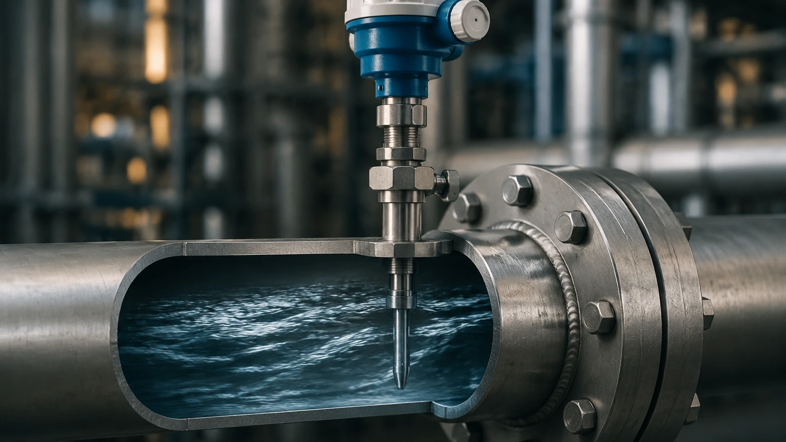
An insertion flowmeter functions by placing a sensor probe through a nozzle or valve into the flow stream. Unlike inline meters that encompass the entire pipe diameter, the insertion probe measures "point velocity." This velocity is then converted into a total flow rate based on the pipe's internal cross-sectional area and the fluid's flow profile. Several distinct technologies are used to achieve this.
1. Electromagnetic Principle
Based on Faraday’s Law of Induction, electromagnetic insertion flowmeters are used for conductive liquids. The probe head contains coils that generate a magnetic field. As a conductive liquid (such as water or chemicals) flows through this field, it generates a voltage proportional to its velocity. This voltage is picked up by electrodes on the probe tip. This method is highly reliable as it has no moving parts and creates negligible pressure drop.
2. Thermal Dispersion
Thermal insertion flowmeters are primarily used for gas flow measurement. The probe features two Resistance Temperature Detectors (RTDs). One RTD acts as a reference, measuring the fluid temperature, while the other is heated to a constant differential temperature above the reference. As gas flows past the heated sensor, it carries away heat. The electrical power required to maintain the temperature differential is directly proportional to the mass flow rate of the gas. This technology is valued for its ability to measure low flow rates and provide direct mass flow data without additional pressure or temperature compensation.
3. Turbine and Vortex Principles
Mechanical insertion flowmeters use a small turbine wheel or a bluff body to create vortices. In a turbine model, the fluid's kinetic energy rotates a rotor at a speed proportional to the flow velocity. In a vortex model, the probe head sheds vortices as fluid passes; the frequency of these vortices is measured by a piezoelectric sensor. These are often used in clean liquids or steam applications where high repeatability is required.
4. Ultrasonic (Transit-Time)
Insertion ultrasonic flowmeters utilize two transducers inserted into the pipe. They send ultrasonic pulses back and forth. The pulse traveling with the flow moves faster than the one traveling against it. The difference in transit time is used to calculate the fluid velocity. This is an excellent choice for large pipes where high accuracy is needed across a wide range of velocities.
Technical Selection Criteria
Choosing the correct insertion flowmeter requires a detailed analysis of the process environment. Because these meters rely on point velocity, they are more sensitive to flow profile disturbances than full-bore meters. The following table summarizes the primary selection factors for common industrial technologies.
Selection Comparison Table
| Technology | Suitable Fluids | Typical Accuracy | Pressure Rating | Key Advantage |
| :— | :— | :— | :— | :— |
| Electromagnetic | Conductive liquids, wastewater | ±1.0% to ±2.0% | Up to 40 bar | No moving parts; low maintenance |
| Thermal | Compressed air, nitrogen, CO2 | ±1.5% of reading | Up to 20 bar | Direct mass flow; high turndown |
| Turbine | Clean water, light oils | ±1.0% | Up to 100 bar | Excellent repeatability |
| Vortex | Saturated steam, high-temp gas | ±1.5% to ±2.0% | Up to 60 bar | Robust in high temperatures |
| Ultrasonic | Clean or slightly dirty liquids | ±1.0% to ±3.0% | Up to 40 bar | Wide measurement range |
Fluid Properties and Pipe Material
Engineers must confirm the chemical compatibility of the probe materials. Most insertion probes are constructed from 316L stainless steel, but aggressive chemicals may require Hastelloy or PTFE coatings. Additionally, the pipe material (carbon steel, PVC, or ductile iron) affects how the mounting hardware—such as the weld-on nozzle or saddle—is attached.
Installation Considerations and Best Practices
Correct installation is the most significant factor in the performance of an insertion flowmeter. Because the meter measures velocity at a single point, the flow profile must be "fully developed" (symmetrical and stable) at the point of measurement.
Straight Pipe Requirements
To ensure a stable flow profile, the meter must be installed in a straight section of pipe away from pumps, valves, elbows, or reducers. A general engineering rule is to have at least 10 diameters (10D) of straight pipe upstream and 5 diameters (5D) downstream. If the upstream disturbance is a pump or a partially closed valve, the requirement may increase to 20D or 30D.
Insertion Depth
The probe must be inserted to a specific depth to capture the average velocity. In a fully developed turbulent flow, the average velocity typically occurs at approximately 1/8th of the pipe diameter or at the center line, depending on the manufacturer's calibration. Precise measurement of the pipe's internal diameter (ID) and wall thickness is mandatory for accurate flow calculation.
Hot Tapping Capabilities
One of the primary benefits of insertion flowmeters is the ability to perform a "hot tap" installation. This process involves welding a thread-o-let or nozzle onto the pipe, attaching a ball valve, and then using a specialized drilling machine to cut a hole in the pipe while it is under pressure. The flowmeter probe can then be inserted through the valve. This eliminates the need for system shutdowns, making it the preferred choice for municipal water systems and 24/7 chemical plants.
Limitations and Potential Risks
While versatile, insertion flowmeters are not universal solutions. Engineers must be aware of the following limitations:
* Flow Profile Sensitivity: Inconsistent flow profiles caused by insufficient straight runs will lead to significant measurement errors. If the flow is laminar or transitional rather than turbulent, the point velocity measurement may not represent the average flow.
* Fouling and Debris: In wastewater or slurry applications, debris can wrap around the probe or coat the electrodes (in electromagnetic models), leading to signal drift or failure.
* Mechanical Stress: In high-velocity applications, the probe is subject to significant drag forces and vibration. If the probe is too long or the velocity too high, it may suffer from mechanical fatigue.
* Air Pockets: For liquid applications, the pipe must be completely full. Air pockets or partially filled pipes will cause the meter to provide erratic or zero readings.
Integration with Level Measurement Systems
In many industrial frameworks, flow measurement and level measurement are two sides of the same coin. For instance, in a large chemical storage tank, a Welk radar level meter provides a precise reading of the current inventory. However, to understand the efficiency of the transfer process, an insertion flowmeter is installed on the intake line.
By comparing the integrated flow data (total volume passed through the pipe) with the change in volume reported by the level transmitter, operators can perform a mass balance. Discrepancies between these two values can alert maintenance teams to leaks, valve failures, or sensor calibration issues. For comprehensive system design, engineers should Review product options and application support to ensure that both level and flow instruments are compatible with the control architecture (e.g., sharing a Modbus or 4-20mA HART loop).
Frequently Asked Questions (FAQ)
Q: Can insertion flowmeters be used for steam?
A: Yes, specifically vortex-type insertion meters. They are designed to withstand the high temperatures and velocities associated with saturated or superheated steam.
Q: What is the minimum pipe size for an insertion meter?
A: While it varies by manufacturer, insertion meters are generally recommended for pipes 80 mm (3 inches) and larger. In pipes smaller than this, the probe itself occupies too much of the cross-sectional area (blockage ratio), which distorts the flow and causes inaccuracy.
Q: How often do these meters require recalibration?
A: For clean fluids, a check every 24 months is standard. In applications with corrosive fluids or high solids content, annual inspection and cleaning of the probe tip are recommended to prevent drift.
Q: Do I need a flow computer?
A: Many modern insertion flowmeters have integrated electronics that output a 4-20mA signal or digital protocol (Modbus/HART) directly. However, for gas or steam applications where pressure and temperature compensation are required to calculate mass flow, a separate flow computer or a PLC-based calculation may be necessary.
Conclusion
The insertion flowmeter remains a cornerstone of industrial fluid management due to its balance of performance and economy. By understanding the specific measurement principles—whether electromagnetic for water or thermal for gases—and adhering to strict installation guidelines regarding straight pipe runs and insertion depth, facilities can achieve reliable data without the high costs of full-bore instrumentation. When combined with advanced level measurement solutions from the Main Page, these flow instruments provide the transparency needed for optimized industrial automation and resource management.