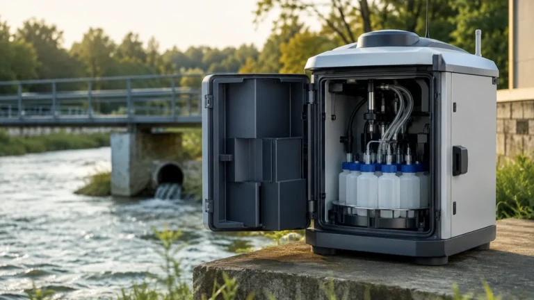
Non Intrusive Flow Meter
Non Intrusive Flow Meter
In modern industrial processing, the ability to measure fluid flow without interrupting operations or compromising the integrity of piping systems is a significant advantage. A non intrusive flow meter, typically utilizing ultrasonic technology, allows engineers to capture accurate flow data from the outside of a pipe. This technology eliminates the need for pipe cutting, welding, or process downtime, making it a preferred choice for retrofitting, temporary audits, and applications involving corrosive or high-pressure media.
For process engineers and facility managers, understanding the underlying physics, selection criteria, and installation nuances of these instruments is critical for ensuring long-term measurement reliability. This guide provides a technical overview of non-intrusive flow measurement, focusing on ultrasonic clamp-on systems.
Understanding Non-Intrusive Flow Measurement Principles
Non-intrusive flow measurement is primarily achieved through ultrasonic transducers clamped to the exterior of a pipe. These sensors transmit and receive acoustic signals through the pipe wall and the moving fluid. There are two primary physical principles used in these devices: Transit-Time and Doppler Effect.
Transit-Time Ultrasonic Principle
Transit-time meters work by measuring the time difference between an ultrasonic pulse traveling with the flow and a pulse traveling against the flow. Two transducers (A and B) serve as both transmitters and receivers.
1. Downstream Pulse: A signal is sent from Transducer A to Transducer B, moving in the same direction as the fluid.
2. Upstream Pulse: A signal is sent from Transducer B to Transducer A, moving against the fluid flow.
Because the fluid carries the sound waves, the downstream pulse travels faster than the upstream pulse. The time difference (Δt) is directly proportional to the velocity of the fluid. Once the velocity is determined, and the internal cross-sectional area of the pipe is known, the volumetric flow rate can be calculated. This method is highly accurate for clean liquids with less than 2% total suspended solids (TSS) or aeration.
Doppler Effect Principle
Doppler flow meters rely on the frequency shift of a reflected ultrasonic signal. The transducers transmit sound into the fluid, which must contain "reflectors" such as suspended solids or entrained gas bubbles.
When the sound wave hits a moving particle, the frequency of the reflected wave shifts (the Doppler effect). The magnitude of this frequency shift is proportional to the velocity of the particle. This technology is ideal for "dirty" liquids, slurries, and aerated fluids where transit-time signals would be attenuated or blocked.
Key Technologies: Transit-Time vs. Doppler Effect
Choosing between these two technologies depends entirely on the characteristics of the fluid and the specific requirements of the application.
| Feature | Transit-Time Ultrasonic | Doppler Ultrasonic |
| :— | :— | :— |
| Fluid Requirement | Clean liquids (water, oils, chemicals) | Aerated or dirty liquids (slurries, wastewater) |
| Suspended Solids | < 2% by volume | > 100 ppm (parts per million) |
| Accuracy | High (0.5% to 2.0% of velocity) | Moderate (2% to 5% of full scale) |
| Pipe Sizes | DN15 to DN6000 | DN25 to DN6000 |
| Flow Direction | Bi-directional | Usually uni-directional |
| Typical Applications | Potable water, cooling water, deionized water | Raw sewage, mining slurries, paper pulp |
Industrial Selection Criteria and Evaluation
Selecting a non intrusive flow meter requires a detailed review of the installation environment and the pipe properties. Unlike inline meters, the pipe itself becomes part of the measurement circuit.
Pipe Material and Condition
Ultrasonic signals must pass through the pipe wall. Homogeneous materials like carbon steel, stainless steel, copper, and most plastics (PVC, PE, HDPE) are excellent conductors of ultrasound. However, pipes with internal liners (e.g., cement, rubber, or bitumen) can present challenges if there is an air gap between the liner and the pipe wall. Air is a poor conductor of high-frequency sound and will effectively block the signal.
Fluid Properties
For transit-time meters, the fluid must be sonically conductive. High-viscosity fluids or those with high concentrations of bubbles can attenuate the signal. For Doppler meters, the fluid must have enough reflectors to provide a strong return signal but not so many that the signal cannot penetrate the center of the pipe.
Temperature Considerations
Standard transducers typically handle temperatures from -40°C to +120°C. For high-temperature applications (up to 250°C or higher), specialized high-temperature transducers and mounting hardware are required to prevent damage to the piezoelectric elements and to ensure the acoustic coupling agent does not evaporate.
Integration with Level Measurement
In many industrial setups, flow measurement is used in conjunction with level measurement to manage inventory or monitor open-channel flow. For instance, in a tank farm, knowing the flow rate into a vessel allows for cross-verification with the data provided by radar or ultrasonic level sensors. For comprehensive instrumentation solutions, including radar and ultrasonic sensors, engineers can visit the Main Page to review product options and application support.
Installation Best Practices for Accuracy
The performance of a non intrusive flow meter is heavily dependent on the quality of the installation. Because the sensors are not in contact with the fluid, external factors must be controlled.
Straight Pipe Requirements
To ensure a stable and predictable flow profile, transducers should be installed on a straight section of pipe. The standard recommendation is at least 10 diameters (10D) of straight pipe upstream of the sensors and 5 diameters (5D) downstream. If the installation is near a pump or a partially open valve, the upstream requirement may increase to 25D or more to allow turbulence to subside.
Transducer Mounting Modes
There are three common mounting configurations:
1. V-Method: The signals bounce off the opposite pipe wall once. This is the standard for most pipe sizes (DN50 to DN400).
2. Z-Method: Transducers are mounted on opposite sides of the pipe. The signal crosses the pipe once. This is used for large pipes (DN400+) or where the fluid is highly attenuative.
3. W-Method: The signal bounces three times. This is used for very small pipes (DN15 to DN50) to increase the transit time and improve resolution.
Acoustic Coupling
An acoustic coupling agent (grease, gel, or epoxy) must be applied between the transducer face and the pipe wall to eliminate air gaps. In permanent installations, stainless steel straps or clamps are used to maintain constant pressure. For long-term outdoor use, weatherproofing the transducers and cables is essential to prevent signal degradation.
Limitations and Operational Risks
While non-intrusive meters offer significant benefits, they are not a universal solution. Engineers must be aware of the following risks:
* Pipe Scaling and Corrosion: Internal buildup (scale) or heavy external corrosion can scatter ultrasonic signals. In some cases, the pipe surface must be ground smooth before mounting.
* Aeration and Cavitation: Excessive bubbles in a transit-time application will cause a "Signal Lost" error. This often occurs downstream of valves or pumps where pressure drops cause dissolved gases to come out of solution.
* Wall Thickness Uncertainty: Since the meter calculates velocity based on the internal diameter, an incorrect pipe wall thickness entry in the transmitter software will lead to a proportional error in the volumetric flow calculation. Using an ultrasonic thickness gauge to verify the pipe wall is a recommended best practice.
* Reynolds Number Sensitivity: Ultrasonic meters are sensitive to the flow profile (laminar vs. turbulent). Most modern transmitters include automatic compensation for the Reynolds number, but this requires accurate fluid viscosity data.
Frequently Asked Questions (FAQs)
Q: Can a non intrusive flow meter measure gas flow?
A: While most clamp-on meters are designed for liquids, specialized high-power ultrasonic meters exist for gas applications. However, gas flow measurement is significantly more complex due to the low density of the medium and the high acoustic impedance mismatch between the pipe wall and the gas.
Q: How often does the coupling agent need to be replaced?
A: In permanent installations using high-quality silicone-based grease or solid coupling pads, the coupling can last for several years. However, in high-vibration environments or extreme temperature cycles, it should be inspected annually.
Q: Is it possible to measure flow in a partially filled pipe?
A: Standard clamp-on ultrasonic meters require a full pipe to function correctly. If the pipe is partially full, the sound waves will not travel through the air space, and the meter will fail. For partially filled pipes or open channels, a combination of an area-velocity meter or a level-to-flow conversion using a flume or weir is required.
Q: Can these meters be used on plastic pipes?
A: Yes, most plastics are excellent conductors of ultrasound. However, reinforced pipes like GRP (Glass Reinforced Plastic) can be difficult because the glass fibers scatter the sound waves.
Summary of Technical Specifications for Selection
When preparing a specification sheet for a non intrusive flow meter project, ensure the following data points are confirmed:
* Fluid Type: Chemical composition, temperature range, and viscosity.
* Pipe Data: Material, outer diameter (OD), wall thickness, and liner material/thickness.
* Flow Range: Minimum, typical, and maximum expected flow velocities (m/s).
* Output Requirements: 4-20mA, Modbus RTU, Pulse, or HART protocol.
* Environment: Hazardous area classifications (ATEX/IECEx) and ambient temperature extremes.
By adhering to these technical boundaries and ensuring precise installation, non-intrusive flow meters provide a reliable, cost-effective, and low-maintenance solution for modern industrial flow monitoring. Their ability to be installed without process interruption ensures that facilities can maintain high uptime while gaining the critical data needed for process optimization and energy management.