Rtd Heat Trace
Rtd Heat Trace
In industrial process environments, maintaining the temperature of fluids within pipes, tanks, and vessels is critical for operational efficiency, safety, and equipment longevity. One of the most reliable methods for achieving this is through electric heat tracing systems monitored and controlled by Resistance Temperature Detectors (RTDs). The term rtd heat trace refers to the integrated application of these precision sensors within a heat tracing circuit to ensure that the thermal energy applied remains within specific parameters.
For industries dealing with viscous chemicals, oil derivatives, or water treatment processes, temperature fluctuations can lead to solidification, crystallization, or increased viscosity that hampers flow and interferes with instrumentation. This article provides a technical overview of how RTD technology interfaces with heat tracing systems, particularly in the context of supporting accurate level measurement and process control.
Understanding the Principles of RTD Heat Trace Systems
To understand the efficacy of an rtd heat trace configuration, one must first examine the underlying measurement principles of the RTD itself. A Resistance Temperature Detector operates on the physical principle that the electrical resistance of a metal increases as its temperature rises. This relationship is highly predictable and linear over a wide range of temperatures.
The RTD Measurement Principle
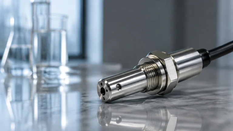
Most industrial RTDs utilize platinum as the sensing element, commonly referred to as PT100 or PT1000 sensors. A PT100 sensor has a resistance of 100 ohms at 0°C (32°F). As the temperature of the pipe or vessel surface changes, the resistance of the platinum wire changes accordingly. A controller or transmitter measures this resistance and converts it into a temperature reading using the Callendar-Van Dusen equation or standard look-up tables (typically following the DIN EN 60751 standard).
In a heat trace application, the RTD serves as the "eyes" of the control system. Unlike self-regulating heat trace cables, which adjust their heat output based on ambient conditions through a conductive polymer core, an RTD-controlled system allows for precise setpoint maintenance. This is essential for processes where the margin for error is narrow, such as preventing the degradation of heat-sensitive chemicals or ensuring that a level meter's signal is not attenuated by vapor or condensation.
Wiring Configurations
RTDs in heat tracing applications are typically found in three wiring configurations:
1. 2-Wire RTDs: These are the simplest but least accurate, as the resistance of the lead wires is added to the sensor resistance, creating an offset error. They are rarely used in critical rtd heat trace systems unless the lead runs are extremely short.
2. 3-Wire RTDs: The industry standard for industrial heat tracing. The third wire allows the controller to measure and subtract the lead wire resistance, providing a much higher degree of accuracy over long distances.
3. 4-Wire RTDs: These provide the highest accuracy by completely eliminating the effect of lead wire resistance. They are typically reserved for laboratory settings or highly critical process points where a fraction of a degree is significant.
The Role of RTDs in Industrial Temperature Maintenance
Heat tracing is not merely about adding heat; it is about thermal management. An rtd heat trace system performs several distinct roles depending on the application requirements.
Freeze Protection
In water treatment and outdoor industrial facilities, heat tracing prevents pipes from freezing. RTDs are used to sense the ambient temperature or the pipe wall temperature. When the temperature drops toward a threshold (e.g., 4°C or 40°F), the RTD signals the controller to energize the heating cables. This prevents the expansion of ice which could rupture pipes or damage sensitive Main Page components like hydrostatic level transmitters.
Process Temperature Maintenance
Many fluids, such as heavy fuel oil, bitumen, or glucose, must be kept at elevated temperatures to remain pumpable. An RTD ensures the heating cable provides exactly enough energy to offset heat loss through the insulation. This prevents "hot spots" that could scorch the product while ensuring the temperature does not drop below the pour point.
Over-Temperature Protection
Even when using self-regulating cables, an RTD is often installed as a safety limit. If the process temperature exceeds the maximum exposure temperature of the heating cable or the safety rating of the vessel, the RTD-based high-limit controller will shut down the circuit to prevent equipment failure or fire hazards.
Integration with Level Measurement Instrumentation
As a manufacturer of industrial level measurement instruments, Welk recognizes that the performance of radar level meters, ultrasonic sensors, and magnetic level gauges is often dependent on the thermal stability of the medium being measured. The rtd heat trace system plays a supportive but vital role in ensuring these instruments provide accurate data.
Preventing Condensation on Sensors
In tanks containing hot liquids, vapor can condense on the cool antenna of a radar level meter or the face of an ultrasonic transducer. This condensation can cause signal attenuation or "false echoes." By heat tracing the nozzle and the mounting flange, and using an RTD to maintain a temperature slightly above the dew point of the vapor, engineers can ensure the sensor face remains dry and functional.
Maintaining Fluidity for Level Accuracy
Hydrostatic level transmitters rely on the density of the liquid to calculate the level. If the temperature of the liquid fluctuates significantly, its density changes, leading to measurement errors. Furthermore, if the liquid becomes too viscous, it may not respond quickly to level changes, or it may clog the sensing diaphragm. An integrated rtd heat trace system maintains a constant temperature, thereby stabilizing the density and viscosity for more reliable level readings.
Protecting Magnetic Level Gauges
Magnetic level gauges (MLGs) feature a float that moves within a chamber. If the liquid in the chamber cools and thickens, the float may stick or move sluggishly. Heat tracing the MLG chamber, monitored by an RTD, ensures the float remains buoyant and responsive to level changes in the primary vessel.
Selection Criteria for RTD Heat Trace Components
Selecting the right components for an rtd heat trace system requires an evaluation of the environment and the process requirements. The following table outlines the key selection criteria for RTD sensors in these applications.
| Criteria | Considerations | Recommendation |
| :— | :— | :— |
| Sensor Type | PT100 vs. PT1000 | PT100 is standard for most industrial controllers; PT1000 offers better resolution for low-power battery applications. |
| Sheath Material | Corrosion resistance | 316 Stainless Steel is standard; Incoloy or Teflon coatings for highly corrosive chemicals. |
| Mounting Style | Contact with surface | Pipe-clamp sensors for external tracing; thermowells for internal process sensing. |
| Accuracy Class | Tolerance levels | Class A (±0.15°C at 0°C) for precise process control; Class B (±0.30°C at 0°C) for general freeze protection. |
| Hazardous Area Rating | Explosion protection | ATEX/IECEx certified sensors and barriers for Zone 1 or Zone 2 environments. |
| Connection Head | Environmental sealing | IP66/IP67 rated aluminum or stainless steel heads to prevent moisture ingress. |
Installation Guidelines and Best Practices
Correct installation is paramount for the accuracy of an rtd heat trace system. If the RTD is not installed properly, it may provide a false reading, leading to either wasted energy or process failure.
1. Sensor Placement: The RTD should be placed at least 90 to 120 degrees away from the heating cable on the pipe circumference. Placing it too close to the cable will result in a reading that is higher than the actual fluid temperature.
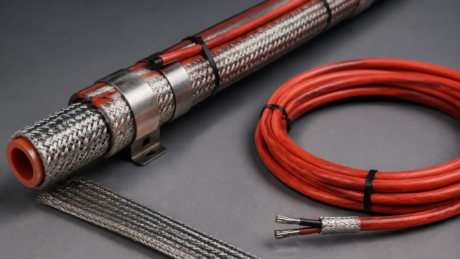
2. Thermal Contact: Use thermal transfer compound between the RTD sensing tip and the pipe wall. Secure the sensor firmly using stainless steel straps or high-temperature glass tape to ensure consistent contact.
3. Insulation Integrity: The RTD and its lead wires must be tucked under the pipe insulation. Ensure that the insulation is not compressed at the sensor location, as this creates a cold spot and skews the reading.
4. Lead Wire Protection: Use conduit or shielded cable for the RTD leads to protect them from mechanical damage and electromagnetic interference (EMI) from nearby power cables.
5. Calibration: Before commissioning, the RTD should be verified against a known standard. In many B2B industrial environments, annual calibration is required to maintain system certification.
Limitations and Common Risks
While rtd heat trace systems are highly reliable, they are not without limitations. Engineering teams should be aware of the following risks:
* Mechanical Stress: RTDs are more fragile than thermocouples. Vibration in piping systems can lead to the fracturing of the internal platinum element if the sensor is not properly supported.
* Moisture Ingress: The most common cause of RTD failure in heat tracing is moisture entering the connection head or the sensor sheath. This can cause a short circuit or a "drift" in resistance, leading to inaccurate temperature control.
* Lag Time: In large vessels or thick-walled pipes, there is a significant time lag between the heating cable energizing and the RTD sensing a temperature rise. This can lead to temperature overshoot if the controller is not properly tuned (PID tuning).
* Point Sensing: An RTD only measures the temperature at one specific point. In long piping runs, multiple RTDs may be necessary to account for variations in flow or ambient exposure.
Frequently Asked Questions
Q: Can I use a thermocouple instead of an RTD for heat tracing?
A: While possible, thermocouples are generally less accurate and more prone to drift over time in the temperature ranges typical for heat tracing (-50°C to 250°C). RTDs provide the stability required for long-term industrial maintenance.
Q: How many RTDs do I need for a 100-meter pipe run?
A: This depends on the process criticality. Typically, one RTD per control circuit is used. If the pipe passes through different environments (e.g., indoors to outdoors), separate circuits and RTDs are recommended.
Q: What is the difference between ambient sensing and pipe sensing?
A: Ambient sensing uses an RTD to measure the outside air temperature to turn on freeze protection for an entire facility. Pipe sensing (or capillary sensing) measures the actual surface of the pipe for precise process maintenance of a specific line.
Q: How does heat tracing affect the lifespan of level meters?
A: When properly controlled via an RTD, heat tracing extends the lifespan of level meters by preventing ice damage, chemical crystallization, and electronic overheating. However, uncontrolled heating can damage sensor electronics.
Conclusion
The implementation of an rtd heat trace system is a foundational requirement for modern industrial thermal management. By providing accurate, stable, and repeatable temperature feedback, RTDs allow heating systems to operate with precision, protecting both the process media and the sensitive instrumentation used to monitor it. Whether ensuring the fluidity of a medium for a Welk radar level meter or preventing a water line from bursting in sub-zero temperatures, the synergy between RTDs and heat tracing cables is essential for operational reliability. For further technical specifications on level measurement solutions that integrate with these systems, engineers are encouraged to review product options and application support on the Main Page.