Pressure Indicating Transmitter
Pressure Indicating Transmitter
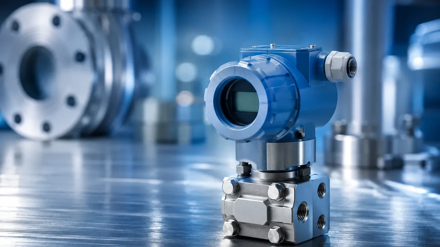
In the landscape of industrial process control, the pressure indicating transmitter stands as a foundational instrument. It performs the dual role of providing a local visual readout of process pressure while simultaneously transmitting a standardized electrical signal to a centralized control system, such as a PLC (Programmable Logic Controller) or DCS (Distributed Control System). This hybrid functionality is critical for both manual monitoring by field operators and automated process regulation.
For engineers and facility managers, selecting the correct pressure indicating transmitter is not merely a matter of measuring force per unit area. It involves understanding the interplay between sensor physics, material science, and the specific requirements of the process environment. This guide provides a technical overview of these instruments, their application in level measurement, and the criteria necessary for reliable industrial integration.
Measurement Principles and Technology
At the core of every pressure indicating transmitter is a sensing element that reacts to physical pressure. This mechanical reaction is converted into an electrical property, which is then processed by the transmitter's internal electronics.
Piezoresistive Sensors
Most modern transmitters utilize piezoresistive technology. These sensors typically consist of a silicon diaphragm with integrated resistors. When pressure is applied, the diaphragm deforms slightly, changing the electrical resistance of the resistors (the piezoresistive effect). This change is proportional to the applied pressure. Piezoresistive sensors are favored for their high sensitivity and stability in standard industrial applications.
Ceramic Thick-Film Sensors
In environments involving aggressive chemicals or abrasive media, ceramic sensors are often preferred. These operate on a similar resistive principle, but the sensing element is printed onto a robust ceramic base. Ceramic is naturally resistant to corrosion and mechanical wear, making it ideal for wastewater treatment or chemical processing where stainless steel diaphragms might fail.
Capacitive Sensors
Capacitive pressure sensors measure the change in electrical capacitance between a sensing diaphragm and a fixed plate. As pressure moves the diaphragm, the distance between the electrodes changes, altering the capacitance. These sensors are known for their exceptional accuracy and are frequently used in high-precision differential pressure applications.
Signal Conditioning and Indication
Once the sensor detects the pressure, the transmitter’s electronics perform signal conditioning. This includes temperature compensation (correcting for the expansion of materials at different temperatures) and linearization. The resulting data is then split into two paths:
1. Local Indication: A digital display (usually LCD or LED) shows the pressure in units such as bar, PSI, or kPa. This allows on-site personnel to verify process status without needing to check the control room.
2. Signal Transmission: The data is converted into a standard 4-20mA analog signal or a digital protocol like HART, Modbus, or Foundation Fieldbus for remote monitoring.
The Role of Pressure Transmitters in Level Measurement
While designed to measure pressure, these instruments are frequently utilized as hydrostatic level transmitters. In the context of industrial automation, measuring the level of a liquid in a tank is often more efficiently achieved by measuring the pressure exerted by the liquid column.
Hydrostatic Principle
The relationship between pressure and level is governed by the formula:
P = ρ × g × h
Where:
* P is the pressure at the bottom of the tank.
* ρ (rho) is the density of the liquid.
* g is the acceleration due to gravity (approx. 9.81 m/s²).
* h is the height of the liquid column.
By knowing the density of the fluid, a pressure indicating transmitter installed at the base of a tank can accurately calculate and display the liquid level. For open-to-atmosphere tanks, a gauge pressure transmitter is used. For pressurized tanks, a differential pressure transmitter is required to subtract the overhead gas pressure from the total pressure at the bottom.
For a comprehensive look at how these technologies integrate into broader industrial systems, you can review product options and application support on our Main Page.
Key Evaluation Criteria for Selection
Selecting a pressure indicating transmitter requires a detailed analysis of the process conditions. The following table summarizes the primary considerations for different sensor types:
| Feature | Piezoresistive | Ceramic | Capacitive |
| :— | :— | :— | :— |
| Typical Accuracy | 0.1% to 0.5% FS | 0.2% to 1.0% FS | 0.05% to 0.1% FS |
| Corrosion Resistance | Moderate (depends on diaphragm) | Excellent (Alumina ceramic) | High |
| Overpressure Limit | Moderate | High | Very High |
| Best Use Case | General oil, gas, and water | Corrosive chemicals, slurries | High-precision laboratory/gas |
| Long-term Stability | Good | Excellent | Superior |
Material Compatibility
The "wetted parts"—those in direct contact with the process media—must be compatible with the fluid. While 316L stainless steel is the industry standard, specialized applications may require Hastelloy C, Monel, or Tantalum coatings for extreme acidity or alkalinity.
Environmental and Safety Ratings
Industrial environments often present harsh conditions. Transmitters should be evaluated based on:
* Ingress Protection (IP): IP65 is standard, but IP67 or IP68 may be required for wash-down areas or submersed applications.
* Hazardous Areas: If the process involves flammable gases or dust, the transmitter must carry ATEX, IECEx, or UL certifications for intrinsic safety or explosion-proof housing.
Installation Considerations
Correct installation is paramount to ensuring the longevity and accuracy of a pressure indicating transmitter. Failure to follow engineering best practices often leads to signal drift or premature sensor failure.
1. Mounting Orientation: For liquid applications, the transmitter should ideally be mounted below the process tap to prevent gas bubbles from being trapped in the impulse line. For gas applications, it should be mounted above the tap to allow condensate to drain back into the process.
2. Impulse Piping: The lines connecting the process to the transmitter should be as short as possible. They should also be sloped (at least 1:12) to prevent the accumulation of air or liquid pockets that can cause false pressure readings.
3. Venting and Bleeding: Always include a manifold or vent valve. This allows the transmitter to be isolated from the process for zero-point calibration and enables the safe bleeding of pressure before removal.
4. Temperature Isolation: If the process temperature exceeds the transmitter's rated operating range (typically above 85°C for standard electronics), use a siphon, cooling tower, or remote capillary seal to protect the sensor.
Limitations and Common Risks
While highly versatile, pressure indicating transmitters have specific limitations that engineers must account for:
* Density Fluctuations: In hydrostatic level applications, if the temperature of the liquid changes significantly, its density will also change. Since the transmitter measures pressure, not actual volume, this can lead to level errors unless temperature compensation is integrated into the control logic.
* Clogging: In applications involving high solids or viscous fluids (like paper pulp or heavy crude), standard pressure ports can clog. In these instances, a flush-diaphragm transmitter is necessary to prevent build-up.
* Overpressure Events: Sudden pressure spikes (water hammer) can permanently deform the sensing diaphragm. Selecting a transmitter with a high overpressure rating or installing a pressure snubber can mitigate this risk.
* Signal Interference: In environments with high electromagnetic interference (EMI), poorly shielded cables can introduce noise into the 4-20mA loop. Using twisted-pair shielded cabling and ensuring proper grounding is essential.
Frequently Asked Questions (FAQ)
Q: What is the difference between a pressure gauge and a pressure indicating transmitter?
A: A pressure gauge is a purely mechanical device for local visualization only. A pressure indicating transmitter provides that local visualization but also converts the measurement into an electronic signal for remote control and data logging.
Q: How often should a pressure indicating transmitter be calibrated?
A: Calibration frequency depends on the criticality of the process and the stability of the instrument. Most industrial standards recommend an annual calibration check, though high-stability sensors may only require adjustment every two to three years.
Q: Can a pressure transmitter measure vacuum?
A: Yes. Absolute pressure transmitters and compound pressure transmitters are designed to measure pressures below atmospheric levels. It is vital to specify the vacuum range during the selection process to ensure the sensor diaphragm can handle the negative pressure.
Q: Does the display affect the power consumption of the loop?
A: Most loop-powered (2-wire) transmitters are designed so that the LCD display consumes very little power, typically operating within the 4mA floor of the signal loop. However, LED displays often require a 3-wire or 4-wire configuration due to higher power demands.
Conclusion
The pressure indicating transmitter is a vital link between the physical process and the digital control system. By providing both immediate field feedback and precise data transmission, it ensures that industrial operations remain safe, efficient, and transparent. When choosing an instrument, engineers must prioritize sensor technology, material compatibility, and proper installation to achieve long-term reliability. For those seeking specific technical data or customized measurement solutions, visiting the Main Page provides access to a wide range of industrial instrumentation designed for the most demanding applications.