Flowlines
Flowlines
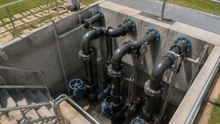
In the context of industrial fluid management and oil and gas production, flowlines represent the critical infrastructure that transports raw fluids from a source—such as a wellhead or a primary storage unit—to a processing facility, manifold, or separator. While the flowline itself is a conduit for transport, the efficiency of the entire system relies heavily on the precise measurement of the fluids within the vessels these lines feed. Monitoring the levels in separators, surge tanks, and storage buffers is essential to prevent overfills, ensure pump protection, and manage the separation of multi-phase fluids.
Understanding the dynamics of flowlines and the subsequent level measurement requirements is a fundamental task for process engineers. This guide explores the technical aspects of flowlines, the principles of level measurement applied to these systems, and the criteria for selecting the appropriate instrumentation for reliable operation.
The Role of Flowlines in Industrial Process Systems
Flowlines are typically the first stage of a gathering system. They carry a mixture of liquids and gases, often under varying pressures and temperatures. Because flowlines often deliver fluids into pressurized vessels like three-phase separators, the level measurement instruments installed on those vessels must be capable of handling the turbulence and phase changes inherent in high-velocity fluid transport.
In chemical processing and water treatment, flowlines connect chemical dosing tanks or raw water sources to treatment basins. In these applications, the flow rate within the flowlines dictates the level fluctuations in the receiving tanks. Without accurate level monitoring, the risk of process interruption or environmental hazards increases significantly. Consequently, the integration of level sensors at the termination points of flowlines is a standard requirement for automated process control.
Measurement Principles for Level Control
Before selecting an instrument for a vessel connected to industrial flowlines, it is necessary to understand the underlying measurement principles. Each technology offers distinct advantages depending on the physical properties of the media and the environmental conditions of the site.
Radar Level Measurement (ToF)
Radar level meters operate on the Time-of-Flight (ToF) principle. The sensor emits a high-frequency electromagnetic wave (typically in the 26GHz or 80GHz range) toward the material surface. The wave reflects off the surface and returns to the antenna. The instrument calculates the distance based on the time it takes for the signal to travel to the surface and back.
* Non-contact Radar: Ideal for corrosive or abrasive fluids delivered by flowlines, as the sensor does not touch the media. It is highly resistant to changes in pressure and temperature.
* Guided Wave Radar (GWR): Uses a probe to guide the signal. This is particularly effective for low-dielectric fluids or applications where the surface might be turbulent due to high-velocity inflow from a flowline.
Ultrasonic Level Measurement
Ultrasonic sensors emit mechanical sound waves. Similar to radar, the distance is calculated based on the reflection time. However, because sound requires a medium (air) to travel, these sensors are sensitive to air temperature, heavy foam, and vacuum conditions. They are most commonly used in water treatment flowlines and open-channel applications where conditions are relatively stable.
Hydrostatic Pressure Measurement
This principle relies on the relationship between the height of a liquid column and the pressure it exerts at the base of a tank. The formula $P = \rho \cdot g \cdot h$ (where $P$ is pressure, $\rho$ is density, $g$ is gravity, and $h$ is height) allows the transmitter to determine the level. This is a robust method for vented tanks but requires compensation if the density of the fluid coming from the flowlines varies significantly.
Magnetic Level Gauges
For high-pressure separators connected to flowlines, magnetic level gauges provide a clear visual indication and can be paired with reed chain transmitters for electronic feedback. They utilize a float containing a magnet that moves with the liquid level, flipping bicolored flaps on an external scale.
Selection Criteria for Level Instruments in Flowline Systems
Choosing the right instrument requires an evaluation of the process conditions at the point where the flowline discharges. The following table provides a comparison of common technologies used in these applications.
| Feature | Radar (80GHz) | Guided Wave Radar | Ultrasonic | Hydrostatic |
| :— | :— | :— | :— | :— |
| Media Type | Liquids/Solids | Liquids/Slurries | Liquids/Grains | Clean Liquids |
| Max Range | Up to 120m | Up to 75m | Up to 30m | Up to 200m |
| Accuracy | ±1mm to ±2mm | ±2mm to ±5mm | ±0.25% of range | ±0.1% to ±0.5% |
| Pressure Limit | High (up to 160 bar) | High (up to 400 bar) | Atmospheric | High (Submersible) |
| Temp. Limit | -40°C to +250°C | -200°C to +450°C | -40°C to +80°C | -10°C to +80°C |
| Foam Resistance | Good | Excellent | Poor | Excellent |
| Turbulence Impact | Minimal | Low | High | Minimal |
When evaluating these options, engineers must confirm the dielectric constant of the fluid, the presence of vapor or steam, and the potential for build-up on the sensor face. For comprehensive technical specifications and product variations, engineers should consult the Main Page of the manufacturer’s catalog.
Installation Considerations and Best Practices
The physical installation of a level sensor relative to the flowline inlet is critical for data integrity. If a sensor is placed directly in the path of the incoming fluid from the flowline, it will likely provide erratic readings due to surface turbulence or physical interference.
1. Nozzle Placement: Sensors should be installed away from the flowline inlet. A common rule of thumb is to maintain a distance of at least 500mm to 1000mm from the inlet pipe to avoid the "splash zone."
2. Stilling Wells and Bypass Chambers: For vessels with extreme turbulence caused by flowlines, installing the sensor (especially GWR or Radar) inside a stilling well or an external bypass chamber can provide a calm surface for measurement.
3. Beam Angle Awareness: For non-contact radar and ultrasonic sensors, the beam angle must be considered. Ensure that the signal path is clear of internal tank structures like ladders, agitators, or the flowline pipe itself.
4. Orientation: Sensors should be mounted vertically. In the case of ultrasonic sensors, ensuring a perpendicular orientation to the liquid surface is vital for receiving a strong return echo.

Limitations and Operational Challenges
While modern instrumentation is highly advanced, certain conditions associated with flowline discharge can present challenges:
* Multi-Phase Fluids: Flowlines often transport a mix of oil, water, and gas. In separators, an emulsion layer (rag layer) may form between the oil and water. Standard radar might reflect off the top layer, whereas Guided Wave Radar is often required to detect the interface between the two liquids.
* High Velocity and Aeration: Rapidly entering fluid can entrain air, creating bubbles or foam. Ultrasonic waves are often absorbed by foam, leading to a "lost signal" error. In these cases, high-frequency radar or hydrostatic sensors are preferred.
* Paraffin and Scale Build-up: In oilfield flowlines, waxes and scales can accumulate on the probes of contact-type sensors. Non-contact radar is the superior choice here to minimize maintenance requirements.
Frequently Asked Questions (FAQ)
Q1: How does the flow rate in the flowline affect level measurement?
High flow rates can cause rapid level changes and surface agitation. This requires a sensor with a fast update rate and signal processing algorithms that can filter out "noise" caused by waves.
Q2: Can one sensor handle different fluids coming from the same flowline?
If the fluids have different dielectric constants, a non-contact radar is generally the most versatile. If using hydrostatic pressure, the system may need recalibration if the fluid density changes significantly.
Q3: What is the maintenance schedule for sensors on flowline-fed tanks?
Non-contact sensors typically require an annual visual inspection. Contact sensors (like GWR probes or floats) may require more frequent cleaning depending on the tendency of the fluid to leave deposits.
Q4: Is it possible to measure the level in a flowline itself?
Flowlines are typically full-pipe systems. Level measurement is usually replaced by flow metering (e.g., electromagnetic or ultrasonic flow meters) within the pipe. Level measurement is reserved for the tanks and vessels where the flowline terminates.
Conclusion
Effective management of industrial processes begins with understanding the relationship between the transport infrastructure—the flowlines—and the storage and processing vessels. Selecting the correct level measurement technology ensures that the transition from transport to processing is monitored with high precision, preventing equipment failure and optimizing throughput. Whether utilizing the precision of 80GHz radar or the ruggedness of hydrostatic transmitters, matching the instrument to the specific dynamics of the flowline discharge is essential for operational success. For detailed application support and to explore the full range of industrial measurement solutions, professionals are encouraged to visit the Main Page for further technical resources.