Flow Line
Flow Line
In the complex landscape of industrial process control, the term "flow line" refers to the critical piping and conduit systems that transport raw or processed fluids between wellheads, storage tanks, processing units, and distribution points. Whether in the oil and gas sector, chemical manufacturing, or water treatment facilities, the integrity and efficiency of a flow line are paramount. However, a flow line does not operate in isolation. To maintain safety and process optimization, it must be integrated with precise instrumentation, specifically level measurement systems that monitor the vessels and separators into which these lines discharge.
Understanding the dynamics of a flow line requires a deep dive into how fluids behave under pressure and how level sensors provide the feedback loop necessary to prevent overflows, pump cavitation, and process interruptions. This guide explores the intersection of flow line management and level measurement technology, providing engineering insights into selection, installation, and maintenance.
Measurement Principles in Flow Line Systems
Before selecting instrumentation for a system connected to a flow line, it is essential to understand the physics behind the primary measurement technologies. In industrial automation, level measurement is generally divided into continuous measurement and point level detection.
Radar Level Measurement (ToF)
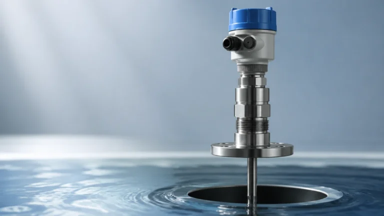
Radar sensors operate on the Time-of-Flight (ToF) principle. The device emits high-frequency electromagnetic waves (typically in the 26GHz or 80GHz range) toward the product surface. These waves are reflected back to the sensor. The distance is calculated based on the time it takes for the signal to travel to the surface and back.
In flow line applications involving separators or surge tanks, non-contact radar is preferred because it is unaffected by pressure, temperature, or the vacuum conditions often found in high-velocity lines. Guided Wave Radar (GWR) is another variation where the signal travels along a probe, making it ideal for low-dielectric fluids or applications with heavy foam.
Ultrasonic Level Measurement
Ultrasonic sensors use sound waves rather than electromagnetic waves. The transducer emits an ultrasonic pulse that bounces off the liquid surface. The time taken for the echo to return determines the level. While cost-effective, ultrasonic measurement is sensitive to air temperature fluctuations and cannot be used in vacuums or high-pressure environments common in many flow line headers.
Hydrostatic Pressure Measurement
This principle relies on the relationship between the height of a liquid column and the pressure it exerts at the base. The formula $P = \rho \cdot g \cdot h$ (where $P$ is pressure, $\rho$ is density, $g$ is gravity, and $h$ is height) allows for accurate level calculation. This is a reliable method for vented tanks connected to a flow line, provided the fluid density remains relatively constant.
Key Evaluation Criteria for Flow Line Instrumentation
When engineering a system to monitor fluids arriving from a flow line, several technical factors must be evaluated to ensure long-term reliability. For a comprehensive overview of available technologies, engineers often consult the Main Page of instrumentation providers to compare specifications.
1. Fluid Characteristics: Is the fluid corrosive, viscous, or prone to coating? For example, crude oil moving through a flow line may contain paraffin that can build up on contact-based sensors.
2. Process Conditions: Flow lines often operate under significant pressure (e.g., 10 bar to 100 bar or 145 psi to 1450 psi). The level instruments installed on associated vessels must be rated for these pressures.
3. Turbulence and Foam: Fluids entering a tank from a high-velocity flow line often create turbulence or surface foam. Non-contact radar with advanced signal processing is typically required to filter out this "noise."
4. Ambient Environment: Industrial flow lines are frequently located outdoors. Instrumentation must have appropriate Ingress Protection (IP66/67) and be capable of operating in extreme temperature ranges, from -40°C to +80°C.
Practical Selection Table
The following table provides a comparison of common level measurement technologies used in conjunction with industrial flow line systems.
| Technology | Best For | Advantages | Limitations |
| :— | :— | :— | :— |
| 80GHz Radar | Narrow tanks, turbulent surfaces | High precision, non-contact, ignores foam | Higher initial cost |
| Guided Wave Radar | Low dielectric fluids, bypass chambers | Unaffected by turbulence, very accurate | Probe can be prone to coating |
| Ultrasonic | Water/Wastewater, open channels | Low cost, easy installation | Sensitive to steam, dust, and vacuum |
| Hydrostatic | Constant density liquids | Simple, reliable, no moving parts | Requires contact, density-dependent |
| Magnetic Gauge | High pressure, visual indication | No power required for visual, robust | Mechanical parts can wear over time |
Installation Considerations for Flow Line Integration
Proper installation is as critical as device selection. When a flow line discharges into a vessel, the placement of the level sensor can determine the success or failure of the measurement.
Avoiding the Fill Stream
The most common error is installing a level sensor directly in the path of the incoming flow line. The force of the fluid can damage probes or create false echoes in radar and ultrasonic systems. Sensors should be positioned away from the inlet or protected by a stilling well.
Nozzle Design
For non-contact radar, the nozzle height and diameter are vital. A nozzle that is too long or too narrow can create "ringing" or internal reflections that interfere with the signal. As a rule of thumb, the sensor should be mounted so that the antenna extends slightly beyond the nozzle bottom into the tank space.
Stilling Wells and Bypass Chambers
In applications where the flow line causes extreme surface agitation, a stilling well (a vertical pipe inside the tank) or a bypass chamber (a pipe mounted outside the tank) is recommended. This creates a calm surface for the sensor to measure, ensuring a stable output for the control system.

Limitations and Common Risks
While modern instrumentation is highly advanced, there are inherent limitations to consider in flow line applications:
* Vapor Space Interference: In chemical flow lines, the accumulation of heavy vapors can slow down the speed of sound, affecting ultrasonic accuracy. Radar is generally immune to this.
* Build-up and Scaling: In mining or wastewater flow lines, material can build up on the sensor face. Periodic maintenance or the use of self-cleaning radar antennas may be necessary.
* Signal Loss: In extremely low-dielectric fluids (like liquefied gases), the radar signal may pass through the liquid rather than reflecting. In these cases, GWR or magnetic level gauges are superior.
Frequently Asked Questions (FAQs)
Q: How does flow velocity in the flow line affect level measurement?
A: High velocity doesn't directly affect the sensor, but it increases turbulence in the receiving vessel. This requires the use of damping settings in the sensor software or physical stilling wells to ensure a steady reading.
Q: Can one sensor handle multiple types of fluids in the same flow line?
A: If the fluids have different densities, hydrostatic sensors will require recalibration. However, radar sensors are generally independent of density and can handle fluid changes without adjustment, provided the dielectric constant remains above a minimum threshold.
Q: What is the maintenance schedule for level sensors on a flow line?
A: Non-contact sensors typically require very little maintenance beyond a yearly visual inspection. Contact-based sensors, such as hydrostatic diaphragms or GWR probes, should be checked every 6 to 12 months for scaling or corrosion, depending on the aggressiveness of the media.
Q: Is it possible to measure level in a horizontal flow line pipe?
A: Yes, point level switches or specialized small-scale radar can be used to detect "pipe full" or "pipe empty" conditions, which is crucial for protecting pumps from running dry.
Conclusion
Managing a flow line effectively requires more than just monitoring the movement of fluid; it requires a holistic approach to the entire process loop. By selecting the correct level measurement technology—whether it be high-frequency radar for turbulent separators or hydrostatic transmitters for bulk storage—engineers can ensure that the flow line remains a productive and safe component of their industrial infrastructure. For further technical specifications and product comparisons, reviewing the Main Page of your equipment provider is a recommended next step in the project planning phase.