
Capacitive Level Probe
Capacitive Level Probe
In the landscape of industrial process control, the capacitive level probe stands as a versatile and robust solution for monitoring the quantity of liquids, powders, and granulated solids within a vessel. Unlike mechanical float switches that rely on moving parts, capacitive sensors utilize electrical properties to determine level, making them suitable for high-pressure, high-temperature, and corrosive environments. This guide provides a comprehensive technical overview of capacitive level measurement, selection criteria, and best practices for industrial implementation.
Measurement Principles of Capacitive Level Probes
To understand how a capacitive level probe functions, one must first understand the basic physics of a capacitor. A capacitor consists of two conductive plates separated by an insulating material known as a dielectric. The ability of this arrangement to store an electrical charge is called capacitance ($C$), which is defined by the formula:
$$C = \epsilon \cdot (A / d)$$
Where:
* $\epsilon$ (Epsilon): The permittivity of the dielectric material between the plates.
* A: The surface area of the plates.
* d: The distance between the plates.
* Main Page Reference: For a broader look at various measurement technologies, you may visit the Main Page of our technical catalog.
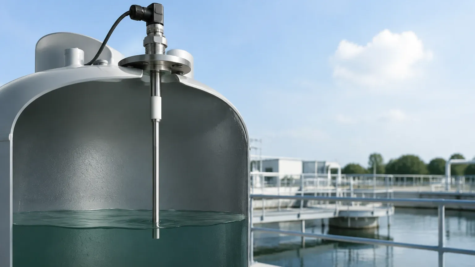
In a level measurement application, the capacitive level probe acts as one electrode (one plate of the capacitor). The second electrode is typically the wall of the metallic tank or a secondary reference rod (grounding sleeve) for non-metallic tanks. The material being measured—whether it is water, oil, or a chemical—acts as the dielectric.
As the level of the medium rises, it displaces the air (which has a dielectric constant $\epsilon_r \approx 1$) with the process material. Since most industrial materials have a higher dielectric constant than air, the total capacitance of the system increases in direct proportion to the level. The internal electronics of the probe convert this change in capacitance into a standardized signal, such as a 4-20mA analog output or a digital switching point.
Conductive vs. Non-Conductive Media
The behavior of the probe changes based on the electrical conductivity of the medium:
1. Non-Conductive Media (e.g., Oils, Hydrocarbons): The material acts as a pure dielectric. The probe is usually a bare metal rod. The change in capacitance is determined by the dielectric constant of the liquid.
2. Conductive Media (e.g., Water-based liquids, Acids): The liquid effectively becomes an extension of the second electrode. To prevent a short circuit, the capacitive level probe must be fully insulated (usually with PTFE or PFA). In this case, the insulation itself acts as the dielectric, and the capacitance changes based on how much of the insulated rod is covered by the conductive liquid.
Types of Capacitive Level Probes
Capacitive sensors are categorized based on their mechanical design and the type of measurement they provide.
Continuous Level Probes
These probes provide a constant signal (e.g., 4-20mA) reflecting the exact level from 0% to 100%. They are ideal for inventory management and process control where precise volume tracking is required. They are available in rod versions for shorter tanks (up to 3-6 meters) and cable versions for deep silos or large storage tanks (up to 30 meters or more).
Point Level Switches
Often referred to as capacitive level switches, these are used for high-level or low-level detection. They do not measure the entire range but rather trigger a relay or transistor output when the material reaches a specific height. These are frequently used for overfill protection or run-dry protection for pumps.
Rod vs. Cable Designs
* Rod Probes: Used for heights typically under 4 meters (13.1 ft). They are rigid and can withstand some level of turbulence or agitation within the tank.
* Cable Probes: Used for deep vessels or where overhead clearance is limited. The cable is weighted at the bottom to keep it vertical. These are common in large grain silos or deep water sumps.
Practical Selection Table
When selecting a capacitive level probe, engineers must match the probe characteristics to the process environment. The following table provides a general guideline for selection.
| Application Feature | Recommended Probe Type | Insulation Material | Considerations |
| :— | :— | :— | :— |
| Non-conductive liquids (Oil) | Bare Rod or Cable | None (Stainless Steel) | Requires stable dielectric constant. |
| Conductive liquids (Water) | Insulated Rod | PTFE / PFA | Insulation prevents short circuits. |
| Corrosive Chemicals | Fully Shielded Probe | PFA / PVDF | Chemical resistance is critical. |
| High-Temperature ( >200°C) | High-Temp Rod | Ceramic / Glass | Specialized electronics housing needed. |
| Solid Powders / Grains | Cable Probe | Reinforced PE / PTFE | Physical abrasion and tensile load. |
| Non-Metallic Tanks | Probe with Ground Tube | N/A | Ground tube acts as the second electrode. |
Key Evaluation Criteria
To ensure the reliability of a capacitive level probe, the following factors must be evaluated during the engineering phase:
1. Dielectric Constant ($\epsilon_r$): This is the most critical factor. If the dielectric constant of the medium is too low (e.g., < 1.5), the change in capacitance may be too small for the sensor to detect reliably. Furthermore, if the $\epsilon_r$ fluctuates significantly due to temperature or composition changes, the measurement accuracy will drift.
2. Vessel Material: If the tank is made of plastic or fiberglass, the probe must include a "reference electrode" or a concentric ground tube to provide a consistent return path for the electrical field.
3. Pressure and Temperature: Capacitive probes are robust, but the seals (typically NPT or Flanged) and the insulation material must be rated for the maximum process pressure (e.g., up to 100 bar) and temperature.
4. Coating and Build-up: In sticky or viscous media, material may cling to the probe even after the level has dropped. Advanced probes use "RF Admittance" or "Active Shield" technology to ignore the capacitance contributed by the coating and measure only the bulk level.
Installation Considerations
Correct installation is paramount to achieving the rated accuracy of a capacitive level probe. Engineers should adhere to the following checklists:
* Mounting Position: The probe should be mounted vertically. If mounted at an angle, the relationship between level and capacitance becomes non-linear, requiring complex calibration.
* Proximity to Walls: In metallic tanks, the probe should be installed at a consistent distance from the wall. If the probe is too close to the wall, the base capacitance increases, which can reduce the sensitivity of the sensor.
* Dead Zones (Null Zones): Every probe has a non-active region at the top (near the mounting thread) and at the very bottom. Ensure that the active length of the probe covers the critical measurement range of your process.
* Grounding: Ensure a low-resistance electrical connection between the probe housing and the metallic tank. For non-metallic tanks, the ground wire must be connected to the reference electrode or ground tube.
* Avoid Turbulence: Do not install the probe directly in the path of the tank's inlet flow. The force of the incoming material can damage the probe or cause erratic readings. Use a stilling well if high agitation is present.
Limitations and Risks
While highly effective, capacitive level probes are not universal solutions. Users should be aware of the following limitations:
* Changing Moisture Content: In solid applications (like grain or sand), a change in moisture content significantly alters the dielectric constant, leading to large measurement errors unless the system is recalibrated.
* Vapor Phase Interference: In some high-pressure steam applications, the dielectric constant of the vapor space can change, affecting the zero-point of the measurement.
* Insulation Damage: For conductive media, any small pinhole or scratch in the PTFE/PFA insulation will cause the probe to short-circuit to the liquid, resulting in a false "high level" reading.
* Heavy Build-up: While active shield technology helps, extremely thick or conductive coatings can eventually overcome the probe's ability to compensate, requiring periodic cleaning.
Frequently Asked Questions (FAQs)
Q: Can a capacitive level probe be used in a plastic tank?
A: Yes, but you must use a probe with a reference electrode (often a ground tube or a second rod). Without a metallic tank wall, the probe needs this second conductive path to form a capacitor.
Q: How do I calibrate a capacitive level probe?
A: Most modern probes feature a two-point calibration. You perform a "Zero" calibration when the tank is empty (or at the lowest desired level) and a "Span" calibration when the tank is full (or at the highest desired level). Some digital probes allow for dry calibration if the dielectric constant of the medium is known.
Q: What is the difference between a capacitive probe and an ultrasonic sensor?
A: Ultrasonic sensors use sound waves and are non-contact, which is good for avoiding corrosive contact. However, they struggle with foam, dust, and vacuum. Capacitive probes are contact-based and are unaffected by dust or vacuum, making them superior for pressurized vessels and powder silos.
Q: Is the probe affected by foam?
A: This depends on the foam's composition. If the foam is light and airy (non-conductive), the probe usually ignores it. If the foam is dense and conductive (like in some chemical processes), the probe may detect it as the liquid level. Specialized RF Admittance probes are better at handling foam.
Conclusion
The capacitive level probe remains a cornerstone of industrial instrumentation due to its lack of moving parts and adaptability to extreme conditions. By understanding the dielectric properties of the process medium and selecting the appropriate insulation and mounting configuration, engineers can achieve highly reliable level monitoring. For those looking to integrate these sensors into a broader automation strategy, reviewing various models and technical specifications on the Main Page is a recommended next step to ensure the chosen hardware aligns with specific application requirements. Proper attention to grounding and material compatibility during the design phase will mitigate the most common risks associated with this technology, ensuring long-term operational stability.


