Tank Level Transmitter
Tank Level Transmitter
In the landscape of industrial automation and process control, the tank level transmitter serves as a critical component for ensuring operational efficiency, safety, and inventory accuracy. These instruments provide continuous measurement of liquid or solid levels within a vessel, converting physical readings into electrical signals—typically 4-20mA, HART, or Modbus—that can be monitored by a PLC or DCS. Selecting the correct technology requires a deep understanding of the underlying physical principles, the properties of the media being measured, and the specific constraints of the installation environment.
Understanding Measurement Principles
Before selecting a tank level transmitter, it is essential to understand how different technologies interact with the process media. Level measurement is generally categorized into non-contact and contact (invasive) methods.
Radar Level Measurement (Non-Contact)
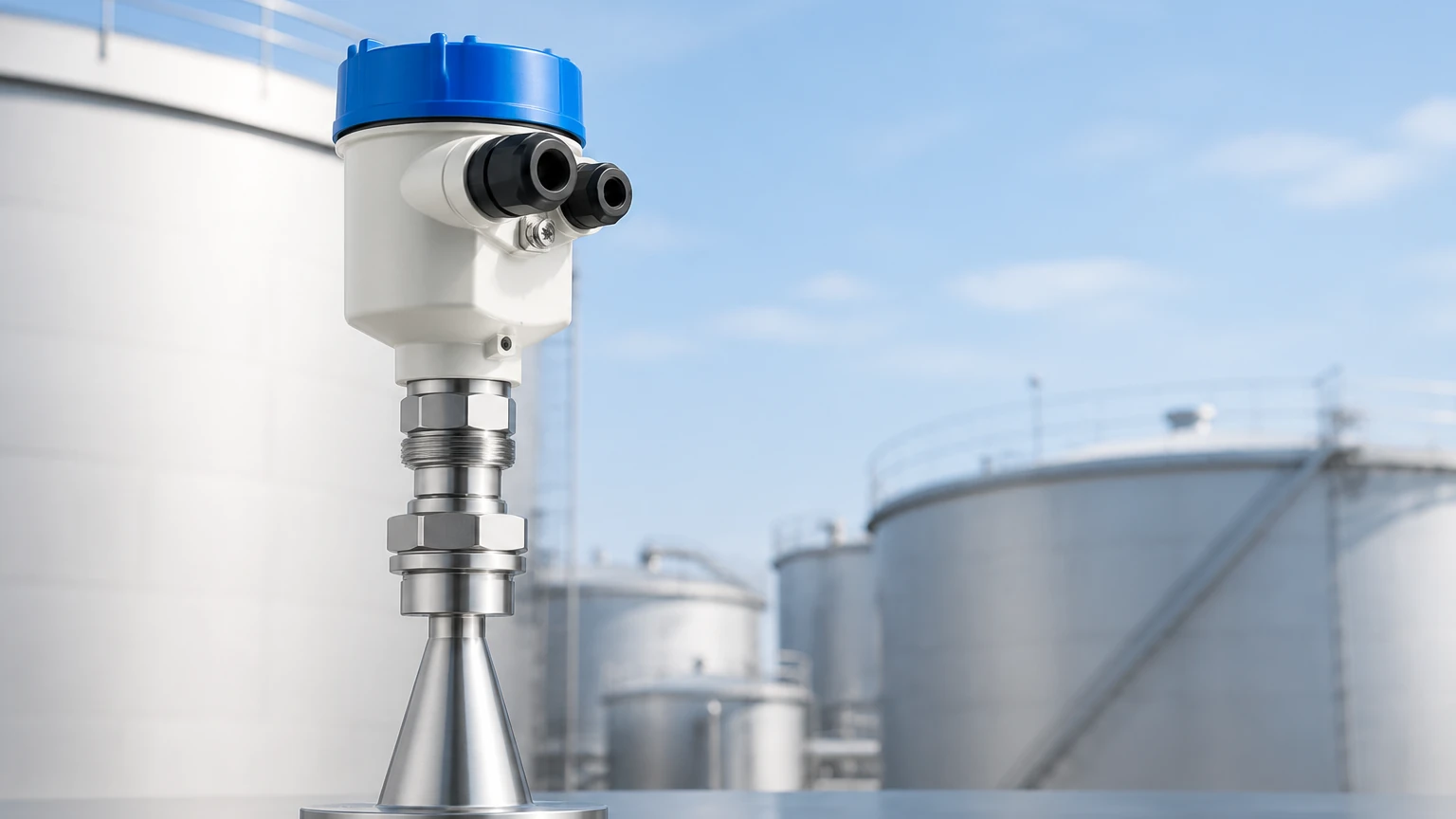
Radar transmitters utilize high-frequency electromagnetic waves, typically in the 26 GHz or 80 GHz range. The device emits a pulse that travels to the surface of the media, reflects, and returns to the sensor. The time-of-flight (ToF) is measured to calculate the distance.
Because radar waves do not require a physical medium to travel, they are unaffected by vacuum, high pressure, or temperature fluctuations. The 80 GHz radar technology is particularly effective for small tanks or vessels with internal obstructions because it offers a narrow beam angle, reducing the risk of false echoes from agitators or ladders.
Ultrasonic Level Measurement (Non-Contact)
Ultrasonic transmitters function similarly to radar but use sound waves instead of electromagnetic pulses. The sensor emits an ultrasonic pulse that reflects off the liquid surface. The speed of sound is the determining factor here.
While cost-effective, ultrasonic measurement is sensitive to the composition of the gas space above the liquid. Since sound speed changes with air temperature and density, these units usually include integrated temperature sensors to compensate for fluctuations. They are ideal for water treatment and simple chemical storage but may struggle in high-pressure or high-dust environments.
Hydrostatic Pressure Measurement (Contact)
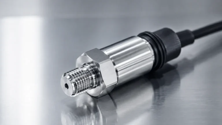
Hydrostatic level transmitters measure the pressure exerted by a liquid column at the bottom of a tank. The principle is based on the formula: $P = \rho gh$, where $P$ is pressure, $\rho$ is the density of the liquid, $g$ is gravity, and $h$ is the height of the liquid.
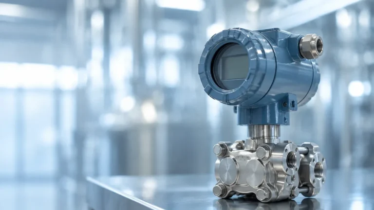
For vented tanks, a simple submersible or flange-mounted pressure transmitter is used. For pressurized vessels, a differential pressure (DP) transmitter is required to subtract the headspace pressure from the total pressure at the bottom. This method is highly reliable but requires the liquid density to remain relatively constant for accurate level calculation.
Magnetic Level Gauges and Transmitters (Contact)
Magnetic level gauges utilize a float containing a permanent magnet that moves with the liquid level inside a bypass chamber. As the float moves, it flips magnetic flaps for visual indication. For electronic transmission, a reed-chain or magnetostrictive sensor is mounted to the outside of the chamber to provide a continuous signal. This technology is preferred for high-temperature, high-pressure, and hazardous media where direct contact with the electronic sensor must be avoided.
Technical Selection Criteria for Tank Level Transmitters
Choosing the right tank level transmitter involves balancing performance requirements against budget and installation constraints. The following table provides a comparison of common technologies used in industrial applications.
| Technology | Media Type | Max Range (Typical) | Best For | Limitations |
| :— | :— | :— | :— | :— |
| Radar | Liquids, Solids, Slurries | Up to 100m | High temp, high pressure, corrosive media | High initial cost compared to ultrasonic |
| Ultrasonic | Liquids, Coarse Solids | Up to 15m – 30m | Water treatment, open channels | Affected by foam, steam, and vacuum |
| Hydrostatic | Clean Liquids, Sludge | Up to 200m (depth) | Vented tanks, deep wells | Density changes affect accuracy |
| Magnetic | Clean Liquids | Up to 6m | Hazardous or high-pressure fluids | Moving parts; prone to scaling |
| Level Switch | Liquids, Solids | Point Level Only | Overfill protection, pump control | No continuous measurement |
When evaluating these options, engineers should consult a comprehensive resource like the Main Page of a specialized manufacturer to review specific model tolerances and chemical compatibility charts.
Installation Best Practices and Geometric Considerations
Correct installation is as vital as the technology choice itself. Even the most advanced tank level transmitter will fail if environmental factors are ignored.
1. The Blind Zone (Dead Band): Every non-contact transmitter has a minimum distance (blind zone) near the sensor face where measurement is impossible. For an ultrasonic sensor, this might be 0.25m to 0.5m. Ensure the transmitter is mounted high enough that the maximum liquid level never enters this zone.
2. Nozzle Dimensions: For radar and ultrasonic units, the mounting nozzle should be as short and wide as possible. A long, narrow nozzle can cause internal reflections that the sensor might mistake for the liquid surface.
3. Internal Obstructions: Avoid mounting transmitters directly above heating coils, agitators, or inlet pipes. If an agitator is present, radar with a narrow beam angle or software-based "false echo suppression" is necessary to filter out the noise.
4. Stilling Wells: In tanks with heavy turbulence or foam, a stilling well (a vertical pipe submerged in the liquid) can provide a calm surface for the transmitter to measure. This is common in oil and gas applications using radar or float-based systems.
Managing Environmental and Media Limitations
Industrial processes rarely involve "ideal" conditions. A robust tank level transmitter must account for the following challenges:
* Foam and Steam: Foam can absorb ultrasonic signals, leading to signal loss. Radar is generally more resistant to foam, though heavy, dense foam may still require a guided wave radar (GWR) approach where the signal travels along a probe.
* Dielectric Constant (dk): Radar relies on the reflectivity of the media, which is determined by its dielectric constant. Hydrocarbons have low dk values (e.g., oil is ~2.0), requiring more sensitive radar electronics compared to water (dk ~80).
* Corrosive Media: For acids and bases, sensors must be constructed from or coated with resistant materials such as PTFE (Polytetrafluoroethylene), PVDF, or high-grade stainless steel (316L or Hastelloy).
* Dust and Build-up: In solid level measurement, dust can attenuate signals. High-frequency radar is often preferred here because it can penetrate dust clouds more effectively than ultrasonic waves.
Maintenance and Calibration Requirements
While many modern transmitters are marketed as "maintenance-free," periodic verification is necessary for ISO compliance and safety.
* Zero and Span Calibration: Hydrostatic transmitters should be checked periodically to ensure the zero point has not shifted due to sensor drift.
* Cleaning: For contact-based systems like magnetic floats or hydrostatic diaphragms, buildup of scale or paraffin can impede movement or distort pressure readings. Regular inspection intervals should be established based on the media's viscosity and tendency to crystallize.
* Signal Validation: Use the digital interface (HART/Modbus) to check the signal strength (echo curve). A weakening signal over time may indicate sensor fouling or an impending hardware failure.
Frequently Asked Questions
Q: Can I use an ultrasonic transmitter in a vacuum tank?
No. Ultrasonic waves require a medium (air or gas) to travel. In a vacuum, there are no molecules to transmit the sound, so the signal will fail. Radar is the preferred choice for vacuum applications.
Q: How does temperature affect hydrostatic level measurement?
Temperature changes affect the density of the liquid. Since hydrostatic transmitters measure weight (pressure), if the density decreases as temperature rises, the transmitter will report a lower level than actually exists unless density compensation is programmed into the control system.
Q: What is the advantage of an 80 GHz radar over a 26 GHz radar?
The 80 GHz radar has a much smaller antenna and a narrower beam (often as small as 3 degrees). This allows it to be installed in smaller nozzles and makes it much easier to avoid hitting internal tank structures like ladders or pipes.
Q: Is a tank level transmitter the same as a level switch?
No. A level transmitter provides a continuous signal (e.g., 0% to 100% full), whereas a level switch provides a binary output (on/off) at a specific point, typically used for high-level alarms or low-level pump protection.
Conclusion
Selecting a tank level transmitter is a balance of physics and practical engineering. By understanding the dielectric properties, pressure requirements, and vessel geometry, operators can select a solution that minimizes downtime and maximizes accuracy. Whether utilizing the precision of high-frequency radar or the reliability of hydrostatic pressure, the right instrument ensures that process variables remain within safe and productive limits. For those beginning a new project or upgrading an existing facility, reviewing technical documentation and product ranges on a dedicated Main Page is the recommended first step in the procurement process.