Intrinsically Safe Level Sensor
Intrinsically Safe Level Sensor
In industrial environments where flammable gases, vapors, or combustible dusts are present, electrical equipment must be designed to prevent accidental ignition. An intrinsically safe level sensor represents a critical component in these safety-instrumented systems. Unlike explosion-proof enclosures that aim to contain an internal explosion, intrinsic safety (IS) is a design technique that limits the electrical and thermal energy available in a circuit to levels below those that could cause ignition of a specific hazardous atmospheric mixture.
For process engineers and instrumentation specialists, selecting the right level measurement technology requires a deep understanding of both the physical measurement principles and the rigorous certification standards that govern hazardous area operations. This guide explores the technical foundations, selection criteria, and installation requirements for intrinsically safe level sensors in modern industrial applications.
Understanding the Principle of Intrinsic Safety
Intrinsic safety is based on the principle of limiting energy. In a typical level measurement loop, the system consists of three primary components: the field device (the sensor), the cabling, and the associated apparatus (usually a Zener barrier or a galvanic isolator located in a safe area).
The protection is achieved by ensuring that even under fault conditions—such as a short circuit or a component failure—the sparks or heat generated by the sensor cannot ignite the surrounding atmosphere. This is particularly vital in "Zone 0" or "Class I, Division 1" environments, where explosive atmospheres are present continuously or for long periods.
The Entity Concept
To ensure a system is intrinsically safe, engineers utilize the "Entity Concept." This involves matching the electrical parameters of the level sensor with those of the safety barrier. The key parameters include:
- Ui (Maximum Input Voltage): The maximum voltage that can be applied to the sensor without voiding its safety rating.
- Ii (Maximum Input Current): The maximum current the sensor can receive.
- Pi (Maximum Input Power): The maximum power the sensor can dissipate.
- Ci (Internal Capacitance): The total equivalent internal capacitance of the sensor.
- Li (Internal Inductance): The total equivalent internal inductance of the sensor.
For a safe installation, the barrier's output parameters (Uo, Io, Po) must be less than or equal to the sensor's input parameters (Ui, Ii, Pi), and the sum of the sensor's Ci/Li plus the cable's capacitance/inductance must be less than the barrier's allowable limits (Co/Lo).
Core Measurement Principles for Hazardous Areas
Before selecting a specific intrinsically safe level sensor, it is essential to understand the underlying measurement physics. Different technologies interact with the process media and the environment in distinct ways.
1. Radar Level Measurement (Non-Contact)
Radar sensors, particularly Frequency Modulated Continuous Wave (FMCW) or Pulsed Radar, are widely used in hazardous areas. They emit high-frequency electromagnetic waves (typically 26 GHz or 80 GHz) that reflect off the surface of the medium. The time-of-flight (ToF) or frequency shift is used to calculate the distance.
In an intrinsically safe configuration, the radar electronics are designed to operate on extremely low power, often utilizing a 2-wire 4-20mA loop. Because radar does not require contact with the medium, it is ideal for corrosive or volatile chemicals where mechanical failure could lead to leaks.
2. Ultrasonic Level Measurement
Ultrasonic sensors use piezoelectric crystals to emit sound waves. The sensor measures the time it takes for the pulse to return after hitting the liquid surface. While cost-effective, ultrasonic sensors in hazardous areas face limitations. The speed of sound is affected by air temperature and the composition of vapors (such as heavy hydrocarbons), which can lead to inaccuracies unless properly compensated. Furthermore, the high-voltage pulses required to drive the transducer must be carefully managed within the IS circuit limits.
3. Hydrostatic Pressure Measurement
Hydrostatic level transmitters measure the pressure exerted by a liquid column. The pressure is proportional to the height of the liquid and its density ($P = ρgh$). For intrinsically safe applications, these sensors often take the form of submersible probes or flange-mounted transmitters.
The primary challenge here is the vent tube in the cable, which allows the sensor to reference atmospheric pressure. In hazardous zones, this cable must be robustly jacketed to prevent the ingress of flammable gases into the safe area via the vent tube.
4. Magnetic Level Gauges and Switches
Magnetic level gauges use a float containing a permanent magnet that moves with the liquid level inside a non-magnetic chamber. Externally mounted switches or transmitters detect the position of the float. Because the electronics are isolated from the process by a solid metal wall, achieving intrinsic safety is often simpler, focusing on the reed switches or the magnetostrictive transmitter mounted on the outside.
Practical Selection Guide for Industrial Applications
When choosing an intrinsically safe level sensor, engineers must balance process requirements with regulatory compliance. The following table provides a comparison of common technologies used in hazardous locations.
| Technology | Typical Application | Advantages in Hazardous Areas | Limitations |
| :— | :— | :— | :— |
| 80GHz Radar | Chemical reactors, fuel tanks | High accuracy, non-contact, ignores vapors/dust | Higher initial cost |
| Ultrasonic | Wastewater wet wells, open sumps | Low cost, easy installation | Affected by foam and heavy vapors |
| Hydrostatic | Deep wells, vented fuel storage | Reliable, simple electronics | Requires density compensation |
| Magnetostrictive | High-accuracy fuel gauging | Very precise, robust | Contacting method, prone to coating |
| Float Switch | High/Low level alarms | Simple, passive (often "simple apparatus") | Mechanical wear, moving parts |
For a comprehensive overview of industrial instrumentation and to explore specific models tailored to these technologies, engineers can visit the Main Page to review product options and application support.
Key Evaluation Criteria for IS Sensors
Beyond the measurement principle, several factors determine the suitability of an intrinsically safe level sensor for a specific project:
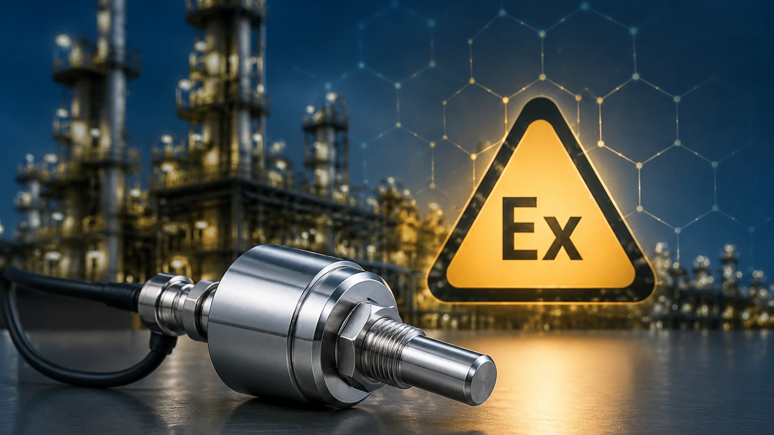
1. Certification Standards: Ensure the device carries the relevant certification for your region, such as ATEX (Europe), IECEx (International), or North American standards (UL/CSA/FM). The label should clearly state the protection level (e.g., Ex ia IIC T4 Ga).
2. Gas Grouping: Hazardous materials are categorized by their ignition energy. Group IIC (Hydrogen/Acetylene) is the most volatile, while IIA (Propane) is the least. A sensor rated for IIC can be used in IIA and IIB environments, but not vice-versa.
3. Temperature Class (T-Code): This defines the maximum surface temperature the device can reach under fault conditions. For example, a T4 rating means the surface will not exceed 135°C (275°F). This must be lower than the auto-ignition temperature of the gases present.
4. Ingress Protection (IP Rating): In many industrial settings, sensors are exposed to heavy rain, washdowns, or dust. An IP67 or IP68 rating is typically required for longevity.
Installation Best Practices and Wiring Standards
The safety of an intrinsically safe system depends entirely on correct installation. Even the best-certified sensor becomes a hazard if wired incorrectly.
Cable Segregation
IS circuits must be physically separated from non-IS circuits. This prevents "creepage and clearance" issues where a high-voltage fault in a non-IS cable could jump to an IS cable. Best practices include using dedicated conduits or cable trays with at least 50mm (2 inches) of separation, or using grounded metal partitions.
Color Coding
In many jurisdictions, intrinsically safe wiring is identified by a light blue jacket. This immediate visual cue alerts maintenance personnel that the circuit requires special handling and that they should not use standard test equipment that might inject unsafe levels of energy into the loop.
Grounding and Bonding
Proper grounding is essential, particularly when using Zener barriers. Zener barriers divert excess energy to the ground, so a high-quality, low-impedance (typically less than 1 Ohm) "IS Ground" is mandatory. Galvanic isolators, which use transformers or opto-couplers to provide isolation, are often preferred in modern plants because they do not require a dedicated high-integrity ground.
Cable Length and Parameters
Every meter of cable adds capacitance and inductance to the circuit. For long cable runs (e.g., over 300 meters or 1000 feet), the accumulated Ci and Li must be calculated to ensure they do not exceed the limits specified by the barrier and the sensor's certification.
Limitations and Environmental Constraints
While intrinsically safe level sensors offer the highest level of safety for Zone 0 environments, they do have inherent limitations:
- Power Constraints: Because the energy is limited, IS sensors cannot power high-intensity displays, internal heaters for de-icing, or high-torque mechanical components. Most IS sensors are 4-20mA loop-powered devices.
- Maintenance Complexity: Testing an IS loop requires specialized, certified handheld communicators or multimeters. Standard tools could potentially trigger an explosion if used while the area is hazardous.
- Cost of Barriers: The requirement for associated apparatus (barriers/isolators) increases the total cost of the loop compared to standard industrial sensors.
Frequently Asked Questions (FAQs)
Q: Can I use an intrinsically safe sensor without a barrier?
A: No. An intrinsically safe sensor is only "safe" when used in conjunction with a certified associated apparatus (barrier or isolator) that limits the energy entering the hazardous area. Without the barrier, the sensor is simply a standard electronic device.
Q: What is the difference between "Ex ia" and "Ex ib"?
A: "Ex ia" is the highest level of protection, capable of maintaining safety even with two simultaneous component faults. It is required for Zone 0. "Ex ib" maintains safety with one component fault and is generally acceptable for Zone 1 or Zone 2.
Q: Is a passive float switch considered intrinsically safe?
A: Simple devices like reed switches, thermocouples, and RTDs are often classified as "Simple Apparatus." They do not need their own IS certification if they do not generate or store more than 1.5V, 100mA, and 25mW. However, they must still be used with an IS barrier to limit the energy from the control system.
Q: Can I use an intrinsically safe sensor in a non-hazardous area?
A: Yes, IS sensors can be used in safe areas. However, it is often more cost-effective to use standard industrial sensors unless the facility wants to standardize on a single model for all applications to simplify spare parts inventory.
Conclusion
Implementing an intrinsically safe level sensor is a fundamental requirement for risk mitigation in the chemical, oil and gas, and wastewater industries. By understanding the electrical parameters of the Entity Concept and choosing a measurement principle—whether radar, ultrasonic, or hydrostatic—that aligns with the physical properties of the media, engineers can ensure both accuracy and safety. Always consult the specific certification documents provided by the manufacturer and adhere to local electrical codes (such as NEC or IEC 60079-14) during the design and installation phases.