Sewer Level Monitoring
Sewer Level Monitoring
Sewer level monitoring is a critical pillar of modern municipal infrastructure and industrial wastewater management. The ability to accurately track the depth, volume, and flow rate of wastewater within a collection system allows engineers to transition from reactive crisis management to proactive, data-driven operations. In the context of increasing urban density and the heightening frequency of extreme weather events, the deployment of robust level measurement instruments is no longer optional; it is a fundamental requirement for environmental compliance, public health, and operational efficiency.
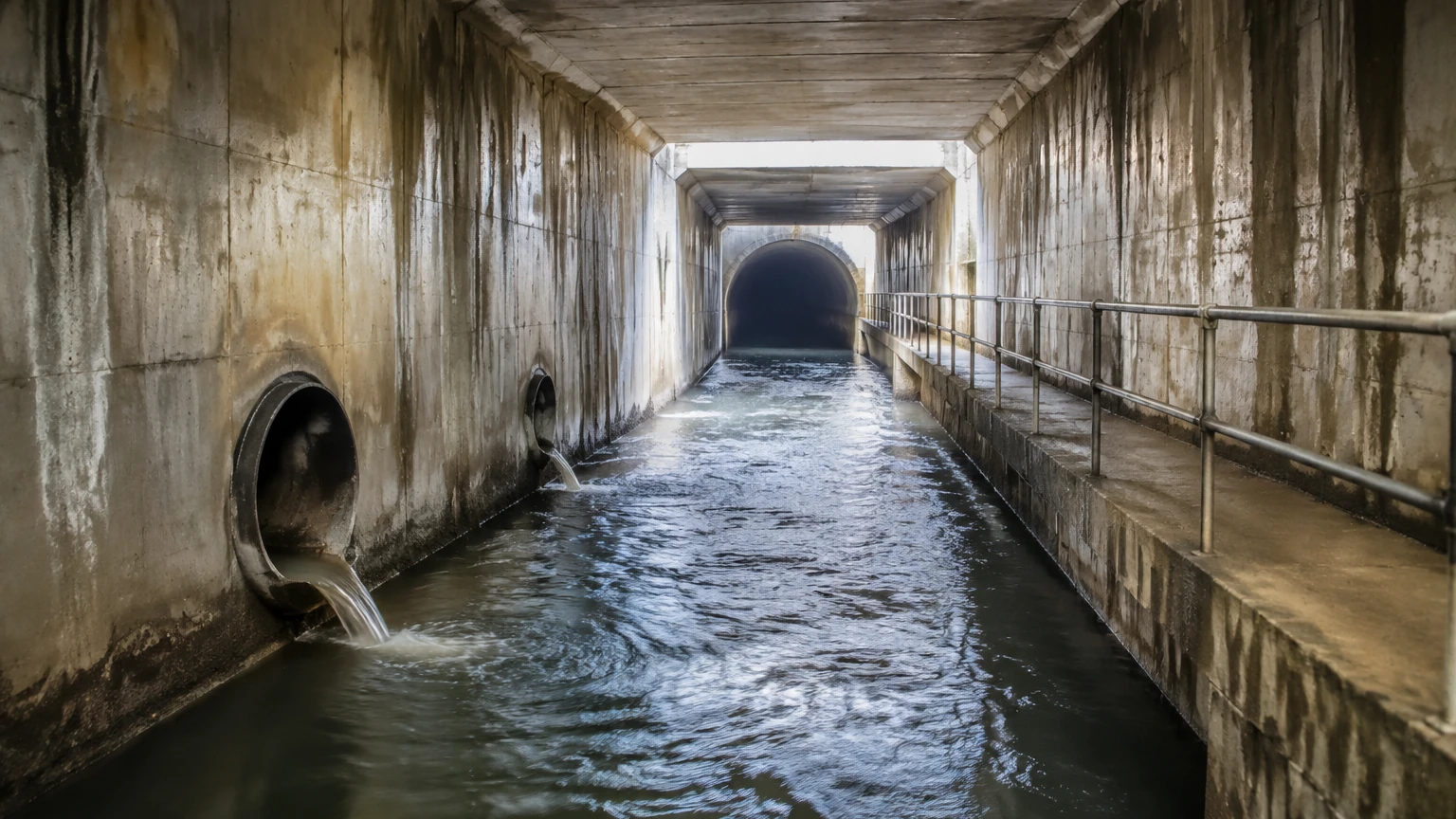
Sewer environments are among the most challenging for instrumentation. Monitoring points—ranging from deep manholes and narrow pipes to massive wet wells and open-channel flumes—present a combination of corrosive gases, high humidity, turbulent flows, and physical debris. This guide provides a comprehensive technical overview of the technologies, selection criteria, and installation strategies required to implement a successful sewer level monitoring program.
Understanding the Core Technologies for Sewer Level Monitoring
Before selecting a device, it is essential to understand the physical principles that govern different measurement technologies. In sewer applications, the choice usually falls between non-contact methods (Radar and Ultrasonic) and contact methods (Hydrostatic and Float switches).
Radar Level Measurement (Non-Contact)
Radar level meters operate on the Time-of-Flight (ToF) principle. The sensor emits high-frequency electromagnetic waves (microwaves), typically at 26 GHz or 80 GHz. These waves travel at the speed of light, reflect off the surface of the wastewater, and return to the sensor. The distance is calculated based on the time elapsed.
Radar is often considered the gold standard for sewer level monitoring because it is unaffected by air temperature, pressure, or the presence of gases like methane and hydrogen sulfide (H2S). Modern 80 GHz radar units offer a very narrow beam angle (often as low as 3 degrees), which allows them to be installed in narrow manholes without interference from internal structures like ladders, pipes, or offset brickwork.
Ultrasonic Level Measurement (Non-Contact)
Ultrasonic sensors also use the ToF principle but utilize sound waves instead of microwaves. The sensor emits a mechanical sound pulse that reflects off the liquid surface. While cost-effective, ultrasonic technology is sensitive to the medium through which the sound travels. Changes in air temperature or the concentration of heavy sewer gases can change the speed of sound, leading to measurement errors. To mitigate this, high-quality ultrasonic sensors must include integrated temperature compensation. Additionally, ultrasonic waves can be absorbed by surface foam, which may result in a lost signal during high-turbulence events.
Hydrostatic Pressure Measurement (Contact)
Hydrostatic transmitters are submersible sensors that measure the pressure exerted by the liquid column above the sensor diaphragm. The principle is defined by the equation $P = \rho \cdot g \cdot h$, where pressure is proportional to the height of the liquid. These sensors are ideal for deep wet wells where surface conditions (like thick foam or heavy steam) might prevent non-contact sensors from getting a clear reading. However, because they are in constant contact with the wastewater, they are prone to fouling from "ragging" (the buildup of fibrous debris) and fats, oils, and grease (FOG).
Magnetic Level Gauges and Switches
While less common for underground pipe monitoring, magnetic level gauges and switches are frequently used in treatment plant tanks and chemical dosing stations. These rely on a magnetic float that moves with the liquid level, providing either a continuous visual indication or a discrete signal at specific setpoints (e.g., high-level alarms).
Environmental Challenges and Selection Criteria
Selecting the right instrument for sewer level monitoring requires a thorough evaluation of the specific site conditions. A sensor that works perfectly in a clean water tank may fail within days in a combined sewer overflow (CSO) structure.
1. Chemical Resistance and Corrosion
Sewer atmospheres are often rich in Hydrogen Sulfide (H2S), which reacts with moisture to form sulfuric acid. This environment is highly corrosive to standard metals. Instruments should ideally be constructed from corrosion-resistant materials such as 316L stainless steel, PVDF, or PTFE. For submersible sensors, the cable jacket material is equally important; polyurethane (PUR) or FEP cables are generally preferred over standard PVC for long-term durability in wastewater.
2. Turbulence and Surface Conditions
In many sewer applications, the water surface is far from calm. Rapidly moving water, falling streams from inlet pipes, and the presence of foam can all interfere with readings. Non-contact sensors like radar are better at penetrating light foam, whereas hydrostatic sensors are unaffected by surface turbulence but must be protected from the physical force of high-velocity flows using a stilling well or protective shroud.
3. Physical Obstructions and Beam Angle
Manholes are often cluttered with internal geometry. If a sensor has a wide beam angle, the signal will bounce off the walls or a ladder before reaching the water. This creates "false echoes." When choosing a radar or ultrasonic sensor, the beam angle must be narrow enough to clear all obstructions. For the most demanding narrow-space applications, the Main Page of technical equipment providers offers detailed specifications on beam divergence and false-signal suppression software.
4. Power Supply and Connectivity
Many sewer monitoring points are located in remote areas without access to the power grid. In these cases, low-power sensors capable of operating on battery or solar power are required. Integration with telemetry systems (such as NB-IoT, LoRaWAN, or cellular 4G/5G) is also a critical consideration for real-time monitoring.
Comparative Analysis of Level Measurement Instruments
The following table provides a practical comparison of the three most common technologies used in sewer level monitoring to assist in the engineering selection process.
| Feature | Radar (80 GHz) | Ultrasonic | Hydrostatic Submersible |
| :— | :— | :— | :— |
| Measurement Type | Non-contact | Non-contact | Contact (Submerged) |
| Accuracy | Highest (±2 mm) | Moderate (±0.25% of range) | High (±0.1% to 0.5%) |
| Gas/Steam Influence | None | Significant (Requires Comp.) | None |
| Foam Influence | Minimal | High (Signal absorption) | None |
| Maintenance | Very Low | Low | Moderate (Fouling risk) |
| Installation | Top-down | Top-down | Bottom-up / Suspended |
| Relative Cost | Higher | Lower | Moderate |
Installation Engineering and Best Practices
Even the most advanced sensor will provide inaccurate data if installed incorrectly. Proper installation in a sewer environment requires attention to both the physics of the sensor and the safety of the technician.
Mounting and Positioning
The sensor should be mounted in a location where the liquid surface is most representative of the overall level. Avoid areas directly above an inlet pipe where falling water will create localized mounding or excessive foam. For non-contact sensors, ensure the face of the transducer is perfectly horizontal (perpendicular to the liquid surface) to ensure the maximum signal return.
Managing the Dead Zone
Every non-contact sensor has a "dead zone" (or blocking distance) directly beneath the transducer where measurements cannot be taken. For example, if an ultrasonic sensor has a 30 cm dead zone, and the water rises to within 20 cm of the sensor, the device will either report an error or a fixed, incorrect value. Engineers must ensure the sensor is mounted high enough that the maximum possible flood level never enters the dead zone.
Submersible Sensor Protection
When installing hydrostatic transmitters, the sensor should not rest directly on the bottom of the channel or wet well, as it will quickly become buried in silt and sludge. Instead, suspend the sensor roughly 10 cm to 20 cm above the floor. Use a stainless steel cable hanger to take the weight off the electrical connection. Furthermore, the atmospheric vent tube in the cable must be kept clear and protected by a desiccant filter to prevent moisture from entering the sensor housing and causing drift.
Safety and Hazardous Areas
Sewers are often classified as Class I, Division 1 or Zone 0/1 hazardous locations due to the potential presence of explosive gases. All instrumentation used in these areas must carry the appropriate intrinsic safety (IS) or explosion-proof (Ex) certifications. Always verify local regulatory requirements before finalizing a hardware selection.
Managing Risks: Maintenance and Signal Integrity
While modern sensors are designed for high reliability, the sewer environment presents ongoing risks that must be managed through a structured maintenance program.
* Condensation: In high-humidity sewer environments, water droplets can form on the face of non-contact sensors. While radar is generally more tolerant of this, heavy condensation can attenuate ultrasonic signals. Choosing sensors with a convex or drip-off transducer face helps shed moisture.
* Fouling and Scaling: For contact-based sensors, the buildup of FOG (fats, oils, and grease) can insulate the diaphragm, leading to sluggish or inaccurate readings. Periodic cleaning with a mild detergent or water jet is necessary.
* Signal Drift: Over time, sensors may experience electronic drift. Regular calibration checks—comparing the sensor output to a manual tape measurement—should be performed at least annually.
* Data Spikes: Turbulent flows can cause rapid fluctuations in the level reading. Implementing "damping" or "averaging" within the sensor's software or the PLC (Programmable Logic Controller) can smooth out these spikes to provide a more usable data trend.
Frequently Asked Questions for Sewer Monitoring Projects
Q: Can radar see through a manhole cover?
A: No. While radar can penetrate some non-metallic materials like plastic or fiberglass, standard cast-iron manhole covers will block the signal. The sensor must be mounted underneath the cover, or a specialized antenna must be used if the electronics are located above ground.
Q: How do I measure flow in a sewer if I only have a level sensor?
A: Level can be converted to flow using a known primary device, such as a flume or weir. By applying the specific head-to-flow formula (e.g., the Manning equation for circular pipes or the Kindsvater-Shen equation for weirs), the level data is transformed into volumetric flow rates (liters per second or cubic meters per hour).
Q: What is the benefit of 80 GHz radar over 26 GHz radar?
A: The primary benefit is the focus. An 80 GHz radar produces a much tighter beam, which reduces the risk of interference from the walls of a narrow pipe or manhole. It also provides better resolution, allowing for more accurate measurements even when the water surface is turbulent.
Q: How long do battery-powered sewer sensors typically last?
A: This depends on the measurement frequency and the transmission interval. A typical setup that takes a reading every 15 minutes and transmits data once an hour can often last 2 to 5 years on a high-capacity lithium battery pack.
Conclusion
Effective sewer level monitoring is a complex engineering challenge that requires a balance of technology, environmental awareness, and rigorous installation standards. By selecting the appropriate measurement principle—whether it be the precision of 80 GHz radar or the ruggedness of a hydrostatic transmitter—operators can gain the visibility needed to prevent overflows and optimize their infrastructure. For those seeking to review specific product options and application support, the Main Page provides a wealth of technical resources and instrument configurations tailored for the wastewater industry. Investing in the right technology today ensures a more resilient and compliant sewer system for the future.