Din Rail Temperature Transmitter
Din Rail Temperature Transmitter
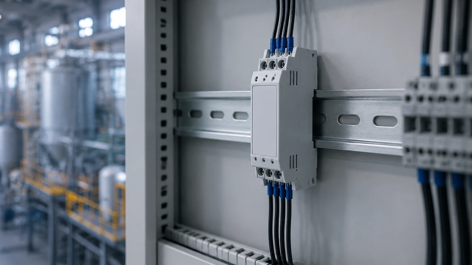
In the landscape of industrial automation and process control, the accurate conversion of raw sensor data into standardized signals is a fundamental requirement. The din rail temperature transmitter serves as a critical bridge between primary temperature sensors—such as Resistance Temperature Detectors (RTDs) and thermocouples—and control systems like PLCs (Programmable Logic Controllers) or DCSs (Distributed Control Systems). By mounting directly onto standard 35mm DIN rails within electrical cabinets, these devices provide a space-efficient, organized, and robust solution for signal conditioning in environments ranging from water treatment plants to complex chemical refineries.
For engineers managing complex liquid monitoring systems, such as those found on the Main Page of industrial instrumentation catalogs, understanding the synergy between temperature and level measurement is vital. Temperature fluctuations directly impact fluid density and the speed of signal propagation, making the integration of a reliable temperature transmitter essential for overall system accuracy.
Measurement Principles and Signal Conversion
Before selecting a transmitter, it is necessary to understand the underlying physics of the sensors it supports. A din rail temperature transmitter does not measure temperature itself; rather, it interprets the electrical changes produced by a sensor and converts them into a linear 4-20mA or digital signal.
Resistance Temperature Detectors (RTD)
RTDs, most commonly the Pt100 or Pt1000 varieties, operate on the principle that the electrical resistance of a metal increases as temperature rises. The transmitter applies a small, constant current to the RTD and measures the resulting voltage drop.
* 2-Wire Connection: Simplest but prone to errors caused by lead wire resistance.
* 3-Wire Connection: The most common industrial standard, using a third wire to compensate for lead resistance.
* 4-Wire Connection: Provides the highest precision by completely eliminating the impact of lead wires, ideal for laboratory-grade or high-accuracy industrial processes.
Thermocouples (TC)
Thermocouples function based on the Seebeck effect, where a junction of two dissimilar metals produces a small millivolt (mV) signal proportional to the temperature difference between the "hot" junction (sensing point) and the "cold" junction (transmitter terminals). The din rail temperature transmitter must perform "Cold Junction Compensation" (CJC) to account for the temperature at the connection terminals, ensuring the output reflects the actual process temperature.
Signal Linearization and Scaling
Raw signals from RTDs and thermocouples are inherently non-linear. A sophisticated din rail temperature transmitter utilizes internal microprocessors and lookup tables to linearize these signals. This ensures that a 12mA output consistently represents the midpoint of the configured temperature range, regardless of the sensor's specific curve.
Key Evaluation Criteria for Selection
Choosing the right transmitter requires a balance between technical specifications and the specific demands of the installation site. The following criteria should guide the procurement process:
1. Input Versatility and Universal Compatibility
Modern transmitters are often "universal," meaning a single unit can be programmed to accept various RTD types (Pt100, Pt500, Ni100) and multiple thermocouple types (K, J, T, E, R, S). This flexibility reduces spare parts inventory and allows for easier field adjustments.
2. Galvanic Isolation
In industrial environments, electrical noise and ground loops can distort sensitive sensor signals. High-quality transmitters offer galvanic isolation (typically rated at 1500V AC or higher) between the input, output, and power supply. This protects the control system from high-voltage surges and ensures signal integrity.
3. Accuracy and Thermal Drift
Accuracy is usually expressed as a percentage of the calibrated span (e.g., ±0.1% or ±0.2°C). However, it is equally important to consider the temperature coefficient or "thermal drift." This measurement indicates how much the transmitter’s accuracy degrades as the ambient temperature inside the control cabinet changes.
4. Configuration Methods
* PC Programmable: Uses software and a USB or proprietary interface for precise calibration and diagnostics.
* DIP Switch/Potentiometer: Offers quick, tool-free setup for standard ranges but lacks the precision and advanced features of software-configured units.
* HART Protocol: Allows for digital communication over the 4-20mA loop, enabling remote diagnostics and configuration via a handheld communicator or PC.
Technical Selection Table
| Feature | Standard Transmitter | High-Performance Universal | Isolated HART Transmitter |
| :— | :— | :— | :— |
| Input Types | Fixed (e.g., Pt100 only) | Universal (RTD, TC, Ohm, mV) | Universal + Digital Comms |
| Isolation | None or Basic | 1500V AC | 2500V AC |
| Accuracy | ±0.2% Span | ±0.1% Span | ±0.05% Span |
| Mounting | 35mm DIN Rail | 35mm DIN Rail | 35mm DIN Rail |
| Configuration | Potentiometer | PC Software | PC / HART Communicator |
| Best For | Simple HVAC/Building Auto | General Process Control | Critical Chemical/Oil & Gas |
Installation and Wiring Considerations
Proper installation is as critical as the device specifications themselves. Failure to follow best practices can lead to signal instability or premature component failure.
Mechanical Mounting
Transmitters should be mounted on a standard 35mm DIN rail (EN 60715). In high-vibration environments, end brackets should be used to prevent the modules from sliding. Ensure there is adequate spacing between units if they are expected to operate at the upper end of their ambient temperature rating to allow for heat dissipation.
Wiring Best Practices
* Shielding: Use shielded twisted-pair cables for both the sensor input and the 4-20mA output. The shield should generally be grounded at only one end (usually the control cabinet side) to avoid ground loops.
* Separation: Route signal cables away from high-voltage power lines and frequency drives (VFDs) to minimize electromagnetic interference (EMI).
* Terminal Torque: Ensure terminals are tightened to the manufacturer's specified torque (typically around 0.5 Nm) to prevent loose connections caused by thermal cycling.
Environmental Protection
While the din rail temperature transmitter is housed inside a cabinet, the cabinet itself must provide the necessary Ingress Protection (IP) rating. For outdoor or wash-down areas, a NEMA 4X or IP66 enclosure is recommended to protect the electronics from moisture and corrosive vapors.
Integration with Level Measurement Systems
In many industrial applications, temperature measurement is not an isolated task but a supporting function for accurate level sensing. This is particularly true for instruments provided by manufacturers like Welk, where precision is paramount.
1. Hydrostatic Level Transmitters: These sensors measure the pressure exerted by a liquid column. Since liquid density changes with temperature, a temperature transmitter provides the data necessary for the PLC to perform density compensation, ensuring the calculated level remains accurate across seasons.
2. Ultrasonic Level Sensors: The speed of sound in air is highly dependent on temperature (changing by approximately 0.6 m/s per degree Celsius). Without accurate temperature compensation—often provided by an external transmitter in large tanks—ultrasonic readings can deviate significantly.
3. Radar Level Meters: While radar is less affected by temperature than ultrasonic waves, extreme temperature shifts can still influence the dielectric constant of certain vapors or the physical integrity of the tank. Monitoring these conditions ensures the radar system operates within its design limits.
Limitations and Common Risks
Despite their reliability, din rail temperature transmitters have limitations that engineers must account for:
* Ambient Temperature Limits: Most transmitters are rated for operation between -40°C and +85°C. In extreme climates or near furnaces, cabinet cooling or heating may be required.
* Response Time: There is a slight delay (typically 100ms to 500ms) as the transmitter filters and processes the signal. This is rarely an issue for temperature (which changes slowly) but should be noted for high-speed control loops.
* Sensor Mismatch: Using a Type K thermocouple with a transmitter configured for Type J will result in massive errors. Always verify that the sensor type, wiring configuration (e.g., 3-wire RTD), and transmitter settings are identical.
* Burnout Detection: If a sensor wire breaks, the transmitter must be configured to drive the output either "High" (e.g., 21.0mA) or "Low" (e.g., 3.5mA) to alert the control system of a failure. Misconfiguring this can lead to dangerous "stuck" readings.
Frequently Asked Questions (FAQ)
Q: Can I use a din rail temperature transmitter with a 2-wire RTD?
A: Yes, but you must usually install a jumper wire between specific terminals on the transmitter to complete the bridge circuit. Note that this configuration will not compensate for lead wire resistance, leading to lower accuracy.
Q: What is the difference between a head-mount and a DIN rail transmitter?
A: A head-mount transmitter is installed directly inside the connection head of the sensor probe. A din rail transmitter is installed in a remote control cabinet. DIN rail units are easier to access for maintenance and are protected from the extreme process temperatures at the sensor point.
Q: How often should a din rail temperature transmitter be calibrated?
A: For most industrial applications, an annual calibration check is standard. However, in highly regulated industries like pharmaceuticals or food production, semi-annual or quarterly calibrations may be required to meet safety and quality standards.
Q: Does the transmitter power the loop?
A: Most 4-20mA transmitters are "loop-powered," meaning they draw their operating power from the same two wires used for the signal. The power is typically provided by the PLC's analog input card or an external 24V DC power supply.
Conclusion
The din rail temperature transmitter is a silent but vital component in modern industrial infrastructure. By converting sensitive, low-level sensor signals into standardized, noise-resistant outputs, it ensures that process controllers receive the accurate data required for safe and efficient operation. Whether used as a standalone monitor or as part of a complex level measurement system, selecting a transmitter with the appropriate isolation, accuracy, and environmental ratings is a fundamental step in engineering a reliable control loop. For those seeking comprehensive measurement solutions, reviewing the technical specifications of both level and temperature instruments on the Main Page is recommended to ensure full system compatibility.