Level Float Switches
Level Float Switches
In the landscape of industrial automation, level float switches represent one of the most reliable and cost-effective technologies for point-level detection. Despite the rise of advanced non-contact technologies like radar and ultrasonic sensors, the mechanical simplicity of a float switch remains a preferred choice for high-low alarms, pump control, and overflow protection across diverse sectors, including water treatment, chemical processing, and oil and gas.
Understanding the engineering principles, material compatibility, and installation requirements is essential for ensuring long-term operational stability. This guide provides a technical overview of level float switches to assist engineers and procurement specialists in selecting the optimal solution for their specific process environments. For a broader look at industrial instrumentation, you can Review product options and application support on our main site.
Fundamental Measurement Principles
Level float switches operate based on Archimedes' Principle of Buoyancy. The core concept is that a floating body will remain on the surface of a liquid or partially submerged, provided its average density is lower than that of the liquid it displaces. As the liquid level rises or falls, the float moves accordingly, triggering a mechanical or electrical change of state.
Magnetic Reed Switch Operation
Most modern industrial float switches utilize a magnetic reed switch mechanism. This design consists of a hollow float containing a permanent magnet and a stationary stem containing one or more hermetically sealed reed switches.
1. Rising Level: As the liquid level increases, the float slides up the stem. When the internal magnet reaches the position of the reed switch, the magnetic field forces the reed contacts to close (or open, depending on the configuration).
2. Falling Level: As the level drops, the float moves away, and the reed switch returns to its original state due to the lack of magnetic influence.
This design is highly valued because the electrical components are completely isolated from the process media, reducing the risk of corrosion and electrical shorts.
Mechanical Microswitch Operation (Tilt Switches)
In larger applications, such as wastewater sumps, cable-suspended float switches are common. These contain a mechanical microswitch and a rolling ball. When the float is hanging vertically (low level), the ball rests away from the switch. As the level rises and the float tilts horizontally or flips over, the ball rolls onto the switch mechanism to trigger the alert.
Common Types of Level Float Switches
Selecting the right switch requires matching the physical configuration to the tank geometry and the nature of the liquid.
1. Vertical Float Switches
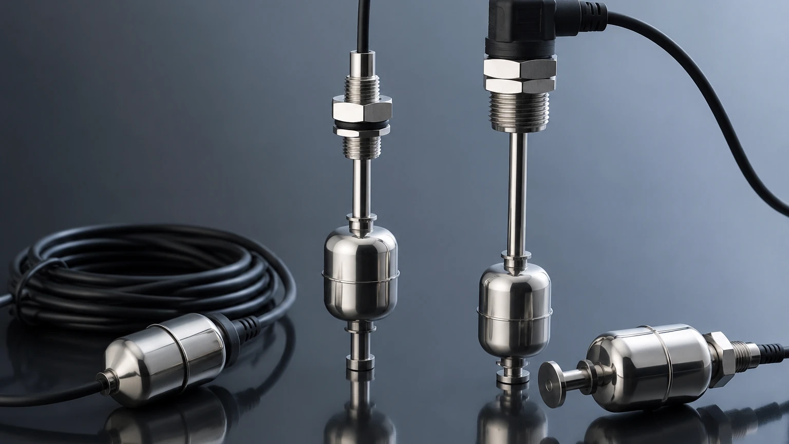
These are mounted through the top or bottom of a vessel. They can be single-point (one float, one switch) or multi-point, where a single stem contains multiple reed switches at different heights to monitor several levels (e.g., Low-Low, Low, High, High-High).
2. Side-Mounted Float Switches
Side-mounted switches are installed through the wall of a tank. They typically use a hinged float arm. When the level reaches the arm, the float rises, pivoting the arm to actuate a microswitch or move a magnet near a reed sensor. These are ideal for tanks where the top is inaccessible.
3. Cable-End (Tilt) Float Switches
Used primarily in open basins, pits, and large tanks, these switches are suspended by their own electrical cable. They are robust and resistant to fouling, making them the standard choice for sewage and water treatment applications.
Technical Selection Criteria
To ensure the longevity of level float switches, several technical parameters must be evaluated during the specification phase.
Material Compatibility
The material of the float and stem must be chemically resistant to the process media.
* Stainless Steel (316L): The industry standard for high-temperature, high-pressure, and food-grade applications. It offers excellent resistance to many chemicals and oils.
* Polypropylene (PP): A cost-effective choice for water, acidic, and alkaline solutions, though limited by lower temperature and pressure thresholds.
* PVDF/PTFE: Reserved for highly aggressive corrosive environments where even stainless steel might fail.
Specific Gravity (SG)
The float must be lighter than the liquid it is intended to measure. Most industrial floats are designed for liquids with a specific gravity of 0.80 or higher. If the liquid is too light (e.g., certain hydrocarbons or liquefied gases), a specialized high-buoyancy float is required.
Temperature and Pressure Limits
Standard plastic switches are often limited to 80°C and 2 bar of pressure. In contrast, heavy-duty stainless steel models can withstand temperatures exceeding 200°C and pressures up to 40 bar (4.0 MPa). Exceeding these limits can cause the float to collapse or the seals to fail.
Electrical Load
Reed switches are generally designed for low-power signaling. Directly switching a high-power pump motor through a reed switch will likely weld the contacts together. It is standard engineering practice to use the float switch to trigger a relay or a PLC input, which then handles the heavy electrical load.
Selection Table: Quick Reference
| Feature | Stainless Steel Vertical | Polypropylene Side-Mount | Cable Tilt Switch |
| :— | :— | :— | :— |
| Max Temperature | Up to 200°C | Up to 80°C | Up to 60°C |
| Max Pressure | Up to 40 bar | Up to 2 bar | Atmospheric |
| Best For | High pressure/Chemicals | Small tanks/OEM | Wastewater/Sumps |
| Durability | Excellent | Moderate | High (against debris) |
| Typical SG | > 0.70 | > 0.85 | > 0.90 |
Installation and Engineering Considerations
Correct installation is critical to prevent false triggering and mechanical failure.
1. Avoid Turbulence: If the tank has an agitator or a high-velocity inlet, the float may bounce, causing "chatter" in the electrical signal. In these cases, a still well (a perforated pipe surrounding the float) should be installed to dampen surface movement.
2. Magnetic Interference: Since many float switches rely on magnets, they should be kept away from strong external magnetic fields or ferrous tank walls that could interfere with the reed switch actuation.
3. Orientation: Ensure vertical switches are perfectly plumb. A tilt of more than 15 degrees can increase friction between the float and the stem, leading to sticking.
4. Wiring Protection: For cable-suspended switches, ensure the cable is secured and not subject to sharp edges that could fray the insulation over time.
Limitations and Operational Risks
While highly reliable, level float switches are not suitable for every application. Engineers should be aware of the following limitations:
* Build-up and Scaling: In liquids that crystallize or contain heavy solids, material can build up on the stem or inside the float. This increases friction and can eventually cause the float to jam in a fixed position.
* Viscosity: Highly viscous liquids (like heavy syrups or crude oil) can impede the movement of the float. For these media, non-contact sensors or hydrostatic transmitters are often better suited.
* Mechanical Wear: Because they are moving parts, float switches eventually succumb to mechanical wear, especially in applications with frequent cycling.
* Contact Protection: Inductive loads (like relay coils) can cause voltage spikes when the switch opens. Installing a snubber circuit or a diode can protect the reed switch contacts from premature failure.
Frequently Asked Questions (FAQ)
Q: Can I use a float switch in a tank with a lot of foam?
A: Yes. One of the advantages of float switches is that they typically ignore foam and react only to the actual liquid level, unlike some ultrasonic or radar sensors that may be confused by foam density.
Q: How do I change the switch from Normally Open (NO) to Normally Closed (NC)?
A: For many vertical float switches, you can simply remove the retaining clip, flip the float 180 degrees, and reinstall it. This reverses the position of the internal magnet relative to the switch.
Q: What is the minimum specific gravity for a standard float?
A: Most standard industrial floats require a specific gravity of at least 0.7 to 0.8. For lighter fluids like LPG, specialized floats with thinner walls or larger volumes are necessary to maintain buoyancy.
Q: How often should float switches be maintained?
A: In clean water applications, an annual inspection is usually sufficient. In wastewater or chemical applications with potential for scaling, quarterly cleaning of the stem and float is recommended to prevent sticking.
Conclusion
Level float switches remain a cornerstone of process control due to their straightforward operation and resilience. By carefully matching material properties, pressure ratings, and installation techniques to the specific needs of the application, operators can achieve highly dependable point-level monitoring with minimal investment.
For complex environments requiring continuous monitoring or non-contact solutions, it is often beneficial to compare these mechanical switches with advanced radar or ultrasonic technologies. For further technical specifications and to explore a full range of industrial measurement tools, please visit our Main Page.