Wastewater Lift Stations
Wastewater Lift Stations
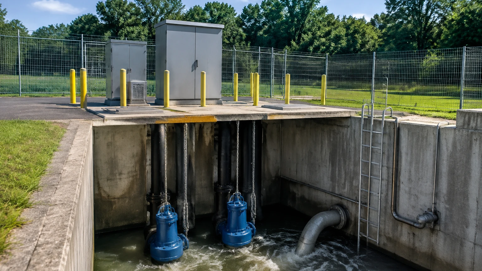
In municipal and industrial infrastructure, wastewater lift stations serve as critical nodes in the collection and transport of sewage and storm water. These systems are designed to pump wastewater from lower to higher elevations when the gradient of the terrain does not allow for natural gravity flow. Because these stations often operate in harsh, corrosive, and remote environments, the reliability of the level measurement instrumentation is paramount to prevent overflows, pump damage, and environmental non-compliance.
Selecting the appropriate technology for monitoring levels in wastewater lift stations requires a deep understanding of the physics of measurement and the specific challenges of the medium. This guide provides a technical overview of measurement principles, selection criteria, and installation best practices for engineering professionals.
Understanding Measurement Principles in Lift Stations
Before selecting a sensor, it is essential to understand the underlying physical principles used to detect liquid levels in a wet well or sump. In wastewater applications, three primary technologies dominate the market: hydrostatic pressure, ultrasonic time-of-flight, and radar (microwave) time-of-flight.
Hydrostatic Level Measurement
Hydrostatic sensors operate on the principle that the pressure at a specific point in a liquid is proportional to the height of the liquid column above it. The relationship is defined by the formula:
P = ρ × g × h
Where *P* is the hydrostatic pressure, *ρ* is the density of the fluid, *g* is the gravitational constant, and *h* is the height of the liquid.
In a lift station, a submersible pressure transmitter is lowered to the bottom of the tank. A flexible diaphragm senses the pressure, which is then converted into an electrical signal (typically 4-20mA). To ensure accuracy, these sensors must compensate for atmospheric pressure changes via a vent tube within the cable.
Ultrasonic Level Measurement
Ultrasonic sensors are non-contact devices that emit high-frequency sound waves toward the surface of the wastewater. The sensor measures the time it takes for the pulse to travel to the surface and reflect back to the transducer. The distance is calculated based on the speed of sound in air.
Because the speed of sound is affected by air temperature, most industrial ultrasonic sensors include integrated temperature compensation. However, they can be sensitive to heavy foam, steam, or significant turbulence, which may scatter the acoustic signal.
Radar Level Measurement
Radar level meters use electromagnetic waves (microwaves) rather than sound waves. Like ultrasonic devices, they measure the time-of-flight of a pulse reflected off the liquid surface. However, radar waves travel at the speed of light and are largely unaffected by air temperature, pressure, or the presence of vapors and gases like Hydrogen Sulfide (H2S).
Modern 80GHz high-frequency radar technology offers a narrow beam angle, which is particularly beneficial in the confined spaces of wastewater lift stations where internal piping, ladders, and pumps could otherwise cause false reflections.
Technology Comparison for Wastewater Applications
Choosing the right technology involves balancing cost, maintenance requirements, and the specific characteristics of the wastewater (e.g., presence of fats, oils, and grease, known as FOG).
| Feature | Hydrostatic | Ultrasonic | Radar (80GHz) |
| :— | :— | :— | :— |
| Measurement Type | Contact (Submerged) | Non-contact | Non-contact |
| Maintenance | High (cleaning required) | Medium (transducer face) | Low |
| Accuracy | ±0.1% to 0.5% FS | ±0.25% of range | ±1 mm to ±2 mm |
| Impact of Foam | None | High (signal loss) | Low to Medium |
| Impact of FOG | High (clogging) | Low | None |
| Corrosion Resistance | Depends on material | Excellent (plastic) | Excellent (PTFE/PVDF) |
| Relative Cost | Low | Medium | High |
Key Evaluation Criteria for Lift Station Instrumentation
When designing or upgrading wastewater lift stations, engineers must evaluate several factors to ensure long-term operational stability.
Chemical and Gas Resistance
Wastewater environments are notoriously corrosive. The presence of organic matter leads to the formation of Hydrogen Sulfide (H2S) gas, which can react with moisture to form sulfuric acid. For contact sensors like hydrostatic transmitters, the housing must be constructed from high-grade stainless steel (316L) or specialized alloys (Hastelloy), and the cable jacket must be resistant to hydrocarbons and acids (typically PUR or FEP). For non-contact sensors, plastic housings or PTFE-faced antennas are preferred.
Turbulence and Surface Conditions
Lift stations often experience high turbulence during pump cycles or when influent enters the wet well. This can cause surface ripples or foam. While hydrostatic sensors are unaffected by surface conditions, they may be buffeted by physical movement if not secured. Non-contact sensors require advanced signal processing algorithms (echo masking) to distinguish the true liquid level from turbulent peaks or foam.
Physical Obstructions
Many wastewater lift stations are crowded with submersible pumps, guide rails, discharge piping, and float switches. When using non-contact sensors, the "beam angle" is a critical specification. A wider beam angle may hit a pump motor or a ladder, resulting in a false high-level reading. High-frequency radar is often the preferred solution here, as its narrow beam (often as small as 3 degrees) can be directed through narrow gaps between equipment.
Installation Considerations and Best Practices
Proper installation is as important as selecting the right sensor. Failure to follow engineering best practices often leads to premature instrument failure or inaccurate readings.
1. Stilling Wells: In extremely turbulent wells, installing a stilling well (a vertical pipe with vent holes) can provide a calm surface for the sensor to measure. This is particularly useful for hydrostatic and ultrasonic technologies. The pipe should be at least 100mm (4 inches) in diameter to prevent clogging from debris.
2. Mounting Location: Sensors should be mounted away from the influent stream to avoid direct impact and excessive turbulence. For non-contact sensors, ensure the device is mounted perfectly perpendicular to the liquid surface.
3. Dead Zones (Blanking Distance): All ultrasonic and radar sensors have a "dead zone" directly beneath the transducer face where measurement is impossible. Ensure the sensor is mounted high enough so that the maximum possible liquid level never enters this zone.
4. Cable Management: For submersible sensors, the cable should be secured with a proper suspension clamp to prevent strain on the internal vent tube. Kinking the vent tube will cause the sensor to provide inaccurate readings as it can no longer compensate for barometric pressure changes.
Common Risks and Maintenance Requirements
The primary risk in wastewater lift stations is the accumulation of Fats, Oils, and Grease (FOG). FOG tends to float on the surface and can coat any object it touches.
* Hydrostatic Sensors: If FOG coats the diaphragm of a hydrostatic sensor, it can add weight or prevent the diaphragm from moving, leading to significant measurement errors. Regular cleaning with a soft cloth and mild detergent is necessary.
* Ultrasonic Sensors: Condensation or grease build-up on the transducer face can dampen the acoustic signal. While many modern sensors feature a self-cleaning effect through vibration, periodic inspection is still required.
* Radar Sensors: These are the least susceptible to build-up, as the microwave signal can typically penetrate thin layers of grease or condensation. However, heavy crusting may eventually require removal.
For engineers seeking to compare specific models and technical specifications for these applications, visiting the Main Page provides a comprehensive overview of available industrial level measurement solutions.
Frequently Asked Questions (FAQ)
Q: Can I use a float switch instead of a continuous level sensor?
A: Float switches are excellent for redundant high-level alarms or simple pump control, but they do not provide the granular data needed for modern SCADA systems, flow calculations, or variable frequency drive (VFD) control. Most modern stations use a continuous sensor (radar/ultrasonic) for primary control and a float switch for emergency backup.
Q: How do I handle H2S gas build-up?
A: Ensure all instrumentation is rated for the appropriate hazardous area (e.g., Class I, Div 1 or ATEX Zone 0/1). Non-contact sensors with encapsulated electronics and plastic housings are generally more resistant to the corrosive effects of H2S.
Q: What is the benefit of 80GHz radar over 26GHz radar in a lift station?
A: The 80GHz radar has a much shorter wavelength, allowing for a smaller antenna and a much narrower beam. This makes it easier to install in small wet wells and reduces the likelihood of interference from internal structures.
Project Confirmation Checklist
Before finalizing the specification for a lift station project, confirm the following data points:
* Maximum and Minimum Level: Ensure the sensor range covers the full depth of the wet well plus a safety margin.
* Tank Geometry: Note the position of all internal obstructions (pumps, pipes, ladders).
* Media Characteristics: Is there a high concentration of FOG? Is foam a frequent issue?
* Connectivity Requirements: Does the local controller or SCADA system require 4-20mA, Modbus RTU, or HART protocol?
* Environmental Rating: Confirm the required IP rating (typically IP68 for submersible or IP67 for top-mounted) and explosion-proof certifications.
By systematically evaluating these factors, facility managers and design engineers can ensure that wastewater lift stations operate efficiently, minimizing the risk of costly overflows and extending the lifespan of the pumping infrastructure.