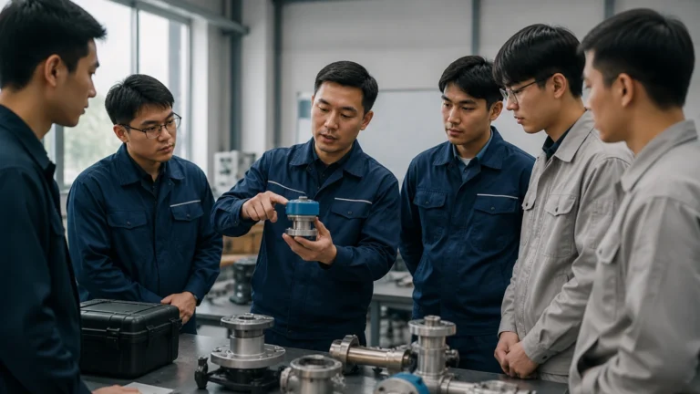
Flowline Installation
Flowline Installation
In industrial process control, the accuracy of level measurement is inextricably linked to the quality of the physical integration of sensors into the piping and vessel architecture. Flowline installation refers to the strategic placement and mounting of level measurement instruments—such as radar, ultrasonic, and hydrostatic sensors—within the fluid transport systems of a facility. Whether dealing with wastewater treatment, chemical processing, or oil and gas production, the integrity of the data collected depends heavily on following standardized engineering practices during the initial setup.
Welk, as a professional manufacturer of industrial level measurement instruments, emphasizes that a successful installation begins with a deep understanding of the underlying physics of the measurement technology. This guide provides a comprehensive technical overview of measurement principles, selection criteria, and the practical steps required for effective flowline installation.
Understanding Level Measurement Principles
Before proceeding with a flowline installation, engineers must evaluate which measurement principle aligns with the physical properties of the media and the environmental conditions of the process. Level measurement technologies generally fall into two categories: contact and non-contact.
Radar Level Measurement (Non-Contact)
Radar level meters operate on the Time of Flight (ToF) principle. The sensor emits high-frequency microwave pulses (typically in the 26GHz or 80GHz range) that travel at the speed of light. When these pulses hit the surface of the medium, a portion of the energy is reflected back to the sensor. The instrument calculates the distance based on the time elapsed between emission and reception.
A critical factor in radar measurement is the dielectric constant ($ε_r$) of the medium. Materials with high dielectric constants, such as water ($ε_r ≈ 80$), reflect signals strongly, while hydrocarbons or dry solids with low dielectric constants ($ε_r < 2$) may require more sensitive equipment or specialized antenna configurations to ensure a reliable return signal.
Ultrasonic Level Measurement (Non-Contact)
Ultrasonic sensors function similarly to radar but use sound waves instead of electromagnetic waves. A piezoelectric crystal within the transducer converts electrical energy into mechanical vibrations, sending an ultrasonic pulse toward the target. The pulse reflects off the surface and returns to the transducer.
Because sound requires a medium to travel, ultrasonic measurements are sensitive to air temperature, pressure, and gas composition. Most modern Welk ultrasonic sensors include integrated temperature compensation to account for changes in the speed of sound, which varies by approximately 0.17% per degree Celsius. However, ultrasonic technology is generally unsuitable for vacuum applications or high-pressure environments where sound propagation is inconsistent.
Hydrostatic Level Measurement (Contact)
Hydrostatic transmitters measure the pressure exerted by a liquid column at a specific point. The principle is based on the formula $P = ρgh$, where $P$ is pressure, $ρ$ is the density of the liquid, $g$ is the gravitational constant, and $h$ is the height of the liquid. By measuring the pressure at the bottom of a tank or within a flowline, the sensor can determine the liquid level if the density remains constant. This method is highly reliable for vented tanks but requires differential pressure measurement if the vessel is pressurized.
Key Criteria for Flowline Installation Selection
Selecting the correct instrument for a flowline installation involves more than just choosing a technology; it requires matching the sensor's physical and electronic specifications to the application's demands. Engineers should evaluate the following criteria:
1. Fluid Characteristics: Is the liquid corrosive, viscous, or prone to foaming? Foaming surfaces can absorb ultrasonic and radar signals, potentially requiring a hydrostatic approach or a guided wave radar.
2. Process Conditions: What are the maximum operating pressures and temperatures? Standard ultrasonic sensors are often limited to 3 bar (43.5 psi) and 80°C (176°F), whereas radar sensors can handle significantly higher extremes.
3. Installation Geometry: Is the sensor being mounted on a narrow pipe, a large tank, or a bypass chamber? The beam angle of the sensor must be narrow enough to avoid reflections from internal obstructions like ladders or agitators.
4. Accuracy Requirements: Does the application require millimeter-precision (common in custody transfer) or is a 1% margin of error acceptable (common in sumps and pits)?
Practical Steps for Flowline Installation
The physical execution of a flowline installation determines the long-term stability and maintenance requirements of the measurement point. Below are the essential considerations for mounting and positioning.
1. Nozzle and Flange Positioning
When installing radar or ultrasonic sensors on a nozzle, the height and diameter of the nozzle must be considered. If the nozzle is too long or too narrow, the signal may reflect off the internal walls of the nozzle before reaching the process media, creating "ringing" or false echoes. Ideally, the sensor's transducer or antenna should extend slightly beyond the bottom of the nozzle to ensure a clear path for the signal.
2. Avoiding Turbulence and Inlets
Sensors should never be installed directly above a filling inlet or in an area of extreme turbulence. The agitated surface can scatter the signal (in non-contact methods) or cause rapid pressure fluctuations (in hydrostatic methods), leading to erratic readings. If turbulence is unavoidable, the use of a stilling well or a bypass pipe is recommended to provide a calm surface for measurement.
3. Alignment and Orientation
For non-contact sensors, the transducer face must be parallel to the liquid surface. Even a few degrees of misalignment can result in the reflected signal missing the receiver, especially in low-dielectric applications. In flowline installation scenarios involving horizontal pipes or slanted tank tops, specialized mounting brackets or gimbal flanges may be necessary to achieve correct perpendicular alignment.
4. Blocking Distance (Dead Zone)
Every ultrasonic and radar sensor has a "blocking distance" or "dead zone" immediately below the sensor face where measurements cannot be taken. During flowline installation, the sensor must be positioned high enough so that the maximum liquid level never enters this zone. Failure to account for this will result in the sensor reporting a full or error state when the level reaches the top of the range.
Technical Comparison Table
To assist in the selection process during a flowline installation project, the following table compares the three primary technologies offered by Welk.
| Feature | Radar Level Meter | Ultrasonic Sensor | Hydrostatic Transmitter |
| :— | :— | :— | :— |
| Measurement Type | Non-contact | Non-contact | Contact |
| Media Compatibility | Liquids, solids, slurries | Liquids, some solids | Liquids only |
| Max Temperature | Up to +450°C (842°F) | Up to +80°C (176°F) | Up to +125°C (257°F) |
| Max Pressure | Up to 160 bar (2320 psi) | Up to 3 bar (43.5 psi) | Up to 40 bar (580 psi) |
| Accuracy | High (±1mm to ±3mm) | Moderate (±0.25% of range) | Moderate (±0.1% to ±0.5% span) |
| Effect of Vapor/Dust | Minimal | Significant | None |
| Cost | Higher | Moderate | Low to Moderate |

Limitations and Common Risks
While modern instrumentation is robust, certain environmental factors can compromise a flowline installation if not addressed during the engineering phase.
* Condensation and Buildup: In humid environments, moisture can condense on the sensor face. While some radar frequencies can penetrate thin films of water, heavy buildup or crystallization can attenuate the signal. Selecting sensors with PTFE-coated antennas or integrated air purge systems can mitigate this risk.
* Internal Obstructions: Pipes often contain heating coils, agitators, or support struts. During flowline installation, it is vital to map these obstructions. Many Welk instruments feature "false echo suppression" software, allowing the user to program the sensor to ignore reflections from fixed internal structures.
* Ambient Noise: In ultrasonic installations, high-frequency acoustic noise from pneumatic valves or heavy machinery can interfere with the sensor's signal. Proper shielding and choosing a sensor with a different operating frequency can resolve these conflicts.
Maintenance and Calibration Post-Installation
Once the flowline installation is complete, the instrument must be commissioned. This involves setting the zero point (empty tank) and the span (full tank). For hydrostatic sensors, this may involve a simple pressure offset. For radar and ultrasonic units, it involves entering the distance from the sensor face to the bottom of the vessel.
Periodic maintenance should include:
* Visual Inspection: Checking for corrosion on flanges and ensuring cable glands remain watertight.
* Cleaning: Removing any material buildup from the transducer or antenna face.
* Verification: Comparing the electronic reading against a manual dip-tape measurement to ensure long-term drift has not occurred.
Frequently Asked Questions (FAQ)
Q: Can I use an ultrasonic sensor in a pressurized flowline?
A: Generally, no. Ultrasonic waves are highly dependent on air density. As pressure increases, the speed of sound changes, and at high pressures, the acoustic impedance mismatch between the sensor and the gas makes signal transmission difficult. Radar or hydrostatic sensors are preferred for pressurized systems.
Q: How does pipe diameter affect flowline installation for radar?
A: If the radar is installed in a narrow pipe (stilling well), the pipe acts as a waveguide. This can actually focus the signal and improve measurement of low-dielectric liquids. However, the pipe must be smooth and free of burrs or welds that could cause interference.
Q: Is it necessary to ground the level instrument?
A: Yes. Proper grounding is essential to protect the electronics from electromagnetic interference (EMI) and static discharge, particularly in plastic tanks or pipes where static can build up from flowing liquid.
Conclusion
Successful flowline installation is a multidisciplinary task that combines fluid mechanics, wave physics, and mechanical engineering. By selecting the appropriate technology and adhering to strict mounting guidelines, industrial operators can ensure accurate, maintenance-free level measurement for years. For detailed technical specifications on our full range of radar, ultrasonic, and hydrostatic sensors, you can visit our Main Page.
Welk remains committed to providing reliable, cost-effective solutions for global industrial automation, backed by rigorous quality control and expert technical support. Whether you are upgrading a legacy system or designing a new facility, proper attention to the details of flowline installation will yield significant dividends in process safety and efficiency.